
- Log in to post comments
 Introduction
This page describes steps needed to run EasyDABv2 board in synchronized network mode. This mode allows boradcasters to extend transmission range of DAB multiplex by adding more transmitters to the network but not adding new frequencies due all transmitters are using same frequency and increases area of same nearby transmitter.
Updated 28.11.2017
This is only progress report. The actual information about final modifications - is located on it's own page!
How it works
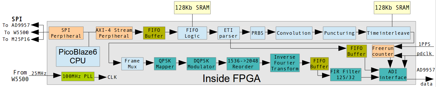
The ETI-parser block has been rewritten to extract TIST field, it keeps information about exact transmission time in milliseconds of current ETI frame. This time counted from the beginning of the second, that is tracked by PPS pulses from GPS receivers. There is also added free-run counter, which will be cleaned-up each 1PPS pulse. If this counter's value will be equal to TIST value, then DAB-frame will start transmitting. Then board repeats this step each frame. Frames that got too late in time will be skipped and not be transmitted. The board will wait for next frame and it's time to transmit. GPSDO 10MHz source is connected to the DAC's reference clock input and internally multiplied to 640MHz by PLL. The incoming samples frequency - is 8.000 MHz, which is used to request I/Q data and also as source for free-run counter.
Needed hardware
- PC with ODR-DabMUX and NTP server (or just with good, synchonized time). In dabmux general config file the option of TIST generation must be enabled. You need to use ZeroMQ input mode on the boards to make stable connection of two modulators to single multiplexor software.
- EasyDABv2 boards. At least 2x of them.
- GPS receivers with 10MHz disciplined clock with so small jitter as possible and 1 PPS outputs.
- Soldering iron and hot-air station to remove unneeded components.
- SPI RAM chip: 23LC1024, it will be used to buffer ETI stream by the boards. It needs to be soldered to X2 connector, more info is described below.
- Oscilloscope that able to show signals up to 200MHz.
Board's modifications
Here is step-by step modification list, that must be done to enable SFN:
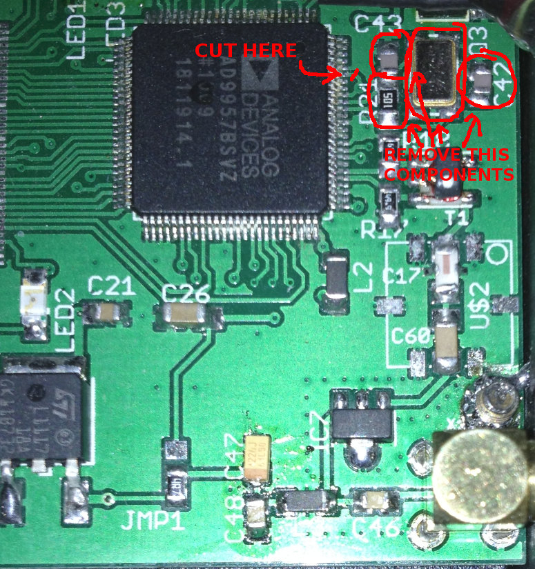
- Unsolder C42, C43, Q3 (24,576MHz), R21.
- Cut the wire on the board, that going to pin 95 of AD9957.
STEPS 1-2 picure (click to enlarge):
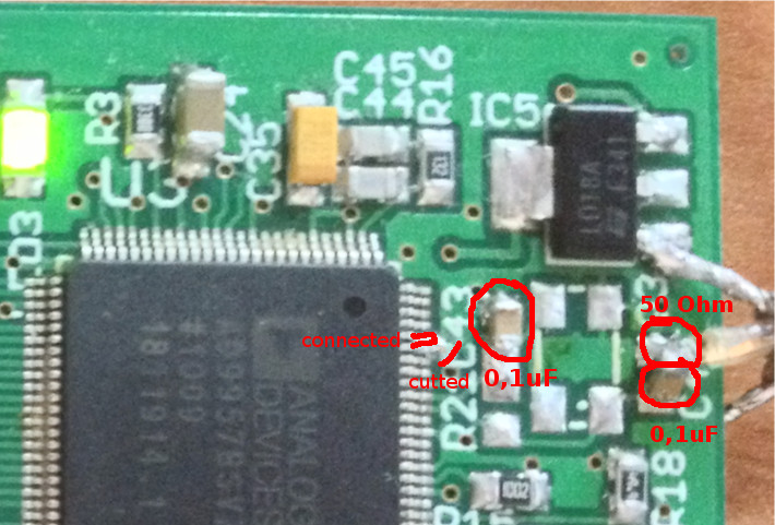
- Connect pins 95 and 96 of AD9957. This way DAC will be switched to external oscillator mode.
- Solder 0,1uF capacitor instead of C43.
- Instead of C42 solder in serial capacitor with 0.1uF and 50 OHm resistor, so this resistor and capacitor will be connected like triangle. Resistor must be connected to GND.
- Connect coaxial cable to the resistor and capacitor (top of triangle), soldered in (5) and this cable will be for 10MHz source.
STEPS 3-6 picure (click to enlarge):
- Install 2 x of 23LC1024 chips to the X2 connector. Interconnection pinouts must be (X2 - at the left, 23LC1024-1 and 23LC1024-2 - at the right):
X2 PIN Description First
23LC1024 PINSecond
23LC1024 PIN1 GND 3,4 3,4 2 SPI MISO 2 2 3 SPI SSn[0] 1 - 4 SPI MOSI 5 5 5 SPI SCLK 6 6 6 1PPS In - - 7 NMEA In - - 8 RESET In/
SPI SSn[1] Out- 1 C50/+3.3V Supply +3.3V 7,8 7,8 Supply with +3,3V can be used from C50 capacitor, that between X2 and SV1 connectors.
Here is result of connection this IC's (click to enlarge):
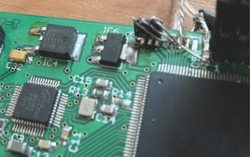
So pins 1,2,3 of SPI-SRAM are directly soldered to pins 3,2,1 of X2. Other pins needs wires to connect. Please note, that in the future there will be needed second 23LC1024 chip, so the 2 x 23LC1024 will provide buffer for up to 1.024 s of buffering. - Connect 1 PPS source to the pin 6 of X2 (throught 1k...6,8K resistor to prevent leaking 5V to the 3,3V schemes).
- Connect NMEA signal output on 9600 baud rate to pin 7. Make sure levels are 3.3V max.
- Provide 10MHz or 30.72MHz, NMEA and 1PPS from GPS to the board (depending on installed firmware).
- Turn on the board.
- Update current firmware to SFN-enabled. It can be downloaded below.
- After successful update, your board is ready to run in SFN mode by requesting data from TIST-enabled ODR-DabMUX by using simple ZeroMQ protocol.
Firmware and source code
ISE project with HDL files: easydabv2.8.SFN-31.05.2016.zip
Ready-made firmware for web-update including update script: easydabv2.8_SFN_firmware-31.05.2016.tar.gz
Known limitations
- Board ignores actual time value, passed by MNSC fields of ETI stream. It only compares TIST and counted pulses. Implementing of this comparison may be added later, but board must know current time somehow (from GPS of from ethernet network) before start broadcasting. For now it works as-is, especially if network latency is not big. The worst-case scenario is that transmissions can not be synchronized correctly, and there will be exactly 1s delay between transmitters.
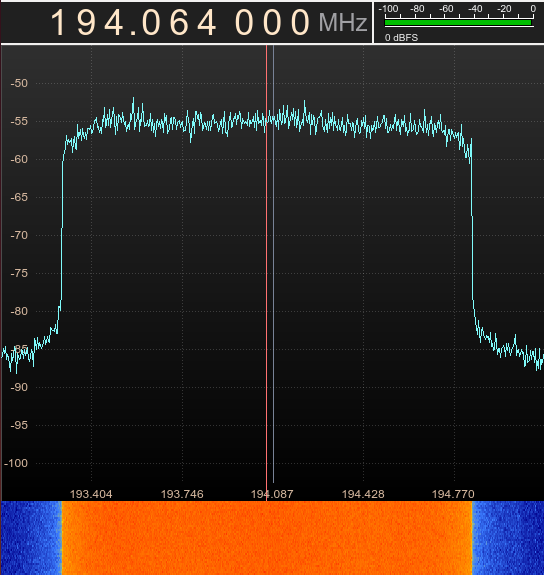
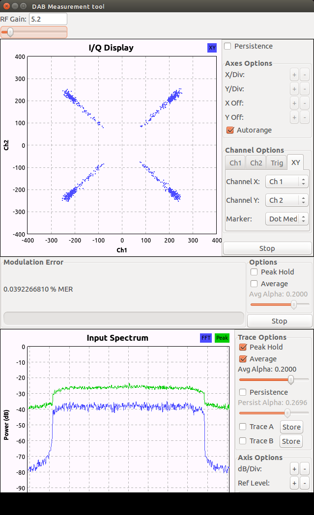
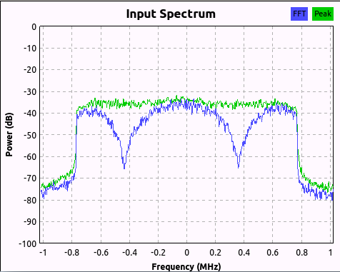
- The output signal's shoulders are not line-like, and it's form is like in image below. This is result of 125x interpolation and then 32x decimation which is enabled because of 10MHz oscillator is used. Maybe it's possible to tune FIR coefficients (amount of coefficents are 1499, because it's response is not very well on too small frequencies). The constellation map of RTL-SDR receiver between 2 boards is on next image.
- The RAM buffer is at least 512 ms size, it's still not very big and can be increased at least twice for even more stable work.
- This implementation is not taking into account fixed delay, that is produced by DAC chip, this delay added during interpolation process inside of DAC itselve.
- Only zero-phase ETI frames time is keeping synchronized (FC.FP == 0). This means that only frames which contains NULL symbol will be started at specified time.
- NULL symbol duration is not taking into account in this firmware, because each 96ms we have time when to start DAB frame, since it's having specific time position to start, so in other time NULL symbol will be transmitted as there is no transmission at this time at all.
- ETI frame's TIST value step - is fixed to 1ms, exactly this step size is produced by ODR-DabMUX. So no need for better resolution of TIST.
- Boards synchronizes during ~500ms after the second transmitter appears on the air. This due timeinterleaver filling itselve by zeroes after powerup. To work-around this in future, during this time frames must be simply skipped. So there will not be gap when second transmitter turned on.
Transmission results
Unfortunaly one of my GPS receivers can't fully lock 10MHz to the satellites, so i'm waiting it's replacement to make real-life tests on-the-air. But it's 10MHz signal quality - is acceptable to start some lab tests and measurements. Delay of 1 PPS signal between two receivers - is less than 70nS, so it's much better than maximum delay between symbols of 300uS, that allowed by the standard.
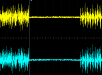
The measuring equipment - is 200MHz oscilloscope with two rays. Yellow ray - is triggering source (trigger setted to video blank field, it's ok to capture null symbol this way). The blue ray - is another one board connected to the second GPSDO.
Here is oscillogram, where NULL symbols between two boards appears synchronously in the time. Next oscillogram shows more detaily view of start of NULL with 4us step (the equal waveforms of the end of previous symbol - are seen in this oscillogram):
Note, that after modificaions, the role of LED1 - will be changed, from now it will blink each time when NULL symbol transmitted (once per 96ms), so it can be used to track synchronisation between the boards. Two boards must blink synchronously.
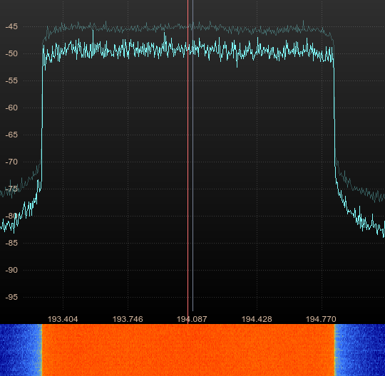
Here is sample of the signal, received in the middle between two transmitters in the lab environment:
Simulated delay of 3uS between transmitters. One of two 10MHz sources - is not locked to GPS.
Update from 22.07.2016:
Got my second GPS-receiver with 10MHz OCXO. Just found the way of tuning delay between 1PPS signals of those GPSDO's. There is parameter "GPS:REF:ADELAY" that can be tuned to set specified "Antenna delay" of the receiver. This param allows to change delay between actual 1PPS and GPS outputted one. So running this command:
UCCM-P > GPS:REF:ADELAY -3E-06
UCCM-P > GPS:REF:ADELAY?
Adds exactly 3us delay to the 1PPS output. This indistrial GPSDO's option adds digital way to better tune DAB SFN signal. The synchronisation strategies are described on page 64 of EBU BPN 066 clause 5.2.3. This is basic How-To for choosing proper delay and distanse between transmitters for SFN. More-less good values for delay - are: -1.8us, -0.8us, -0.3us.
Update from 25.07.2016:
Good news: New sample rate has been presented. Previous filter 125/32 for samplerate of 8000kHz gave -3.14 dB at the shoulder's frequencies (± 768kHz), which makes signal visually less rectangular and more hyperbolar. But now there is better acceptable samplerate frequency: 3200 kHz. So now I'm started using 25/16 interpolation filter: 2048kHz -> 3200kHz. Which have only -1.02dB at the shoulders, and now output signal became more rectangular as before.
Rightnow i'm doing development of enchanced version of time comparator for DAB SFN. As written upper here - it was simplified, and did comparison between TIST values only. But it also needs to compare actual time that encoded on MNSC field. I'm tried to make conversion to use UNIX-timestamp for making comparison, but it needs a lot of multiplications and DSP48 usage is grown too much, so decision to create own wall clock/calendar has been made. The samples on how to do it in FPGA has been found. Rightnow I'm making enchanced version of this comparator between income ETI-stream MNSC+TIST and UTC-time, received by GPS. For this I need to make decision on how internal board's clock will be initialized. There is few ways that I see:
- "Smart way" for receivers like Ublox LEA-M8F or cheap receivers: when board turns on, it receives GPS NMEA $GPRMC messages by serial port:
$GPRMC,081143.000,A,XXXX.XXXX,N,XXXXX.XXXX,E,0.01,XXX.XX,250716,,,A*69
So this message may be parsed and internal wall clock of the board will be setted to this time. Since it's UTC, the leap second is already presented here.
- "Way for mobile BSS GPS receivers" so-called UCCM: The GPS receiver's, that avaliable on EBAY and which I have now - are from mobile base stations, and initially they are not supporting NMEA messages. But we still can get time from it by serial port command "TIME:STRing?":
UCCM-P >TIME:STRing?
2016/07/25 07:49:19

Command complete
UCCM-P >
And it will return GPS time (it's not UTC, because doesn't contains leap seconds, like that which has been presented 1 July 2015). So this may make problem in the future when next leap second will be presented. Also I tried NMEA-like output of Furuno GT-8034F module, that is slodered to SYMMETRICOM UCCM, but it's time - is GPS as wee, and not UTC too, so need to use additional receiver to get UTC time from them.
Other methid - is to parse debug information when "TOD EN" command sent to the receiver, it will answer with debug string each 2 seconds, it contains gps timestamp and amount of seconds offset to get UTC. - Same as previous way, but using debug serial port, avaliable on 50-pin connector <---- this is main job. More info at GPSDO's pinouts page.
- To set-up time from HTTP request, like when ETI-server sending special request to each transmitter to check or set it's current wall clock time. But this variant is actually not very good.
Update from 18.08.2016:
I got UBlox LEA-M8F modules to try as clock source. Here is oscillograms of output signals (30.72MHz sine wave and 1PPS pulse).
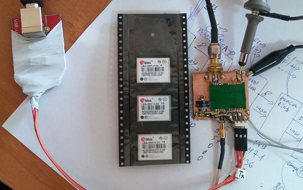
All what is needed for EasyDABv2 is just in small 17x20 mm module. Here is NMEA log and bold-marked values - is what's needed to set wall clock:
$GNRMC,100516.00,A,[POS],N,[POS],E,0.052,,180816,,,A*67
$GNVTG,,T,,M,[POS],N,[POS],K,A*34
$GNGGA,100516.00,[POS],N,[POS],E,1,12,0.90,173.8,M,25.6,M,,*4C
$GNGSA,A,3,[SATINFO],0.90,1.35*1F
$GNGSA,A,3,[SATINFO],0.90,1.35*12
$GPGSV,3,1,[SATINFO],38*73
$GPGSV,3,2,[SATINFO],38*71
$GPGSV,3,3,[SATINFO],32*73
$GLGSV,3,1,[SATINFO],28*6E
$GLGSV,3,2,[SATINFO],10*6C
$GLGSV,3,3,[SATINFO],*5D
$GNGLL,[POS],N,[POS],E,100516.00,A,A*7F
$GNZDA,100516.00,18,08,2016,00,00*7F
Final firmware implemented! Both UCCM and LEA-M8F works just as expected! More details at modifications page.
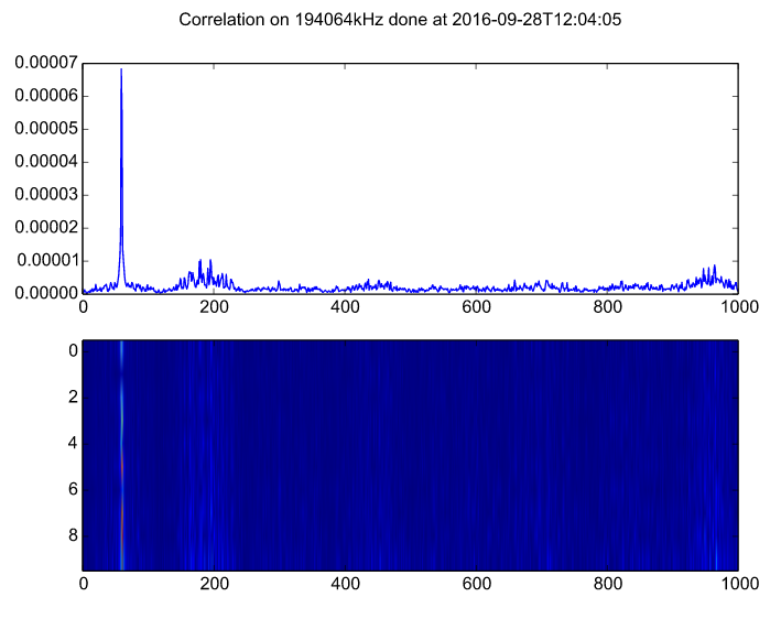
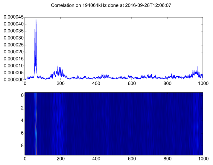
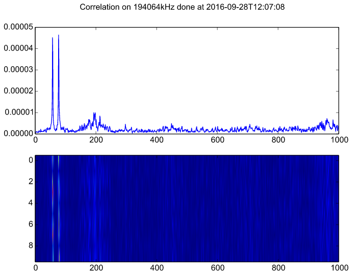
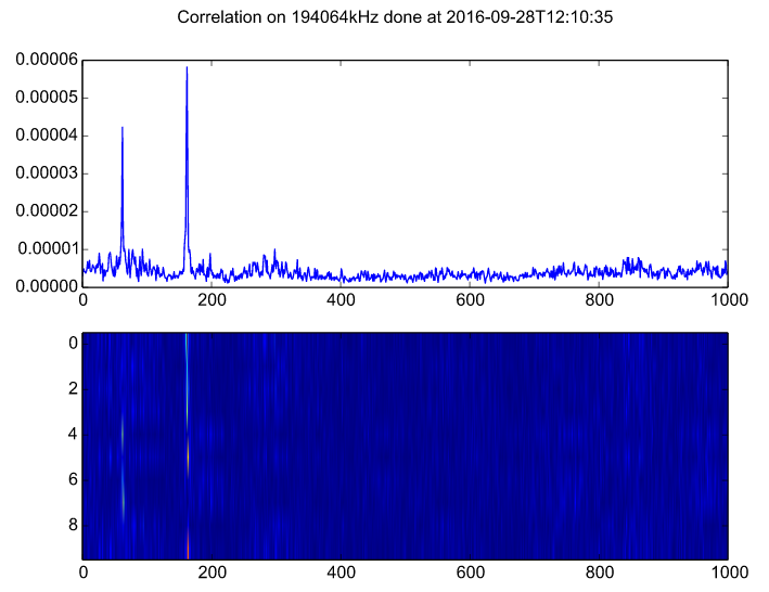
Here is some measurements, done by ODR-DAB-CIR tool, that is fine for seeing channel impulse response, so delay between transmitters can be visually seen.
Here is my test table setup:
- EasyDABv2 SFN-modified with Trimble 57963-C UCCM GPS-receiver. It outputs 10MHz reference plus 1PPS plus UART-debug data with timestamps.
- EasyDABv2 SFN-modified with LEA-M8F receiver. Additional UART-tx pin connected to GPS receiver to force sending reference's locking state.
As result on web-ui there is new parameter: ETI-GPS delay, which can be used to fine-tune delay between timestamp, announced in ETI-stream and actual time to transmit this frame. The more-loaded ETI-frame (higher amount of stations, or higher summar bitrate of them) give lower amount of seconds for buffering. For example: single 128kbps station inside ETI-stream, can be buffered up to ~12 seconds. If You have 6x of 128Kbps stations, You can buffer only up to ~4.5 seconds. Be careful with this parameter. If buffer overflows, then board can hang until it sends this buffer.
Here is simulation results:
| 1st pic: No delay between transmitters | 2nd: 3us delay | 3rd: 10us delay | 4th: 100us delay |
|---|---|---|---|
 |
 |
 |
 |
Enchanced firmware released. Now TCP reconnection is done when connection stucked and don't send any data for a long time. Also "bottleneck" place in Ethernet->PicoBlaze6->BRAM-FIFO has been replaced to DMA, which does direct: Ethernet->BRAM-FIFO data transfer. So it's possible to get stable transmission even without external SPI-SRAM and with good (low delay) internet connection. More info on firmware's page.
Enchanced firmware released. Now EEP-B profile works as expected. Added internal GPSDO schematic and design. Dropped support 10MHz reference clock and UCCM protocol. More info on firmware's page.
Added TII (Transmitter Identification Information) feature. This feature helps to understand which transmitter doing actual broadcasting. Even more, if You are located in area, where multiple transmitters doing broadcasting in SFN, by using TIIdata, You can understand which exactly transmitters You are receiving. For example here is screenshot of QIRX application, which is receiving two EasyDABv2 which is synchronized in SFN at the same time:
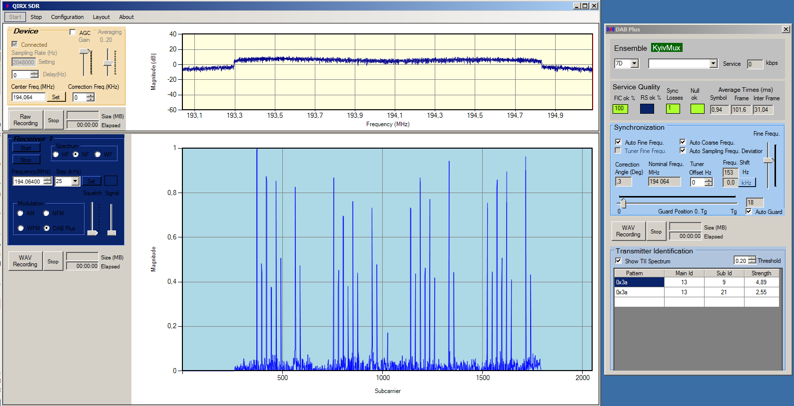
At this demo, there is 2 transmitters with same MainId: 13 (the netwirk id) and each transmitter have it's own SubId: 9 and 21. So there is also difference in strength between 2 transmitters that is detected by the software, so one of them is having higher amplitude and another one - is lower.