
- Log in to post comments
Introduction
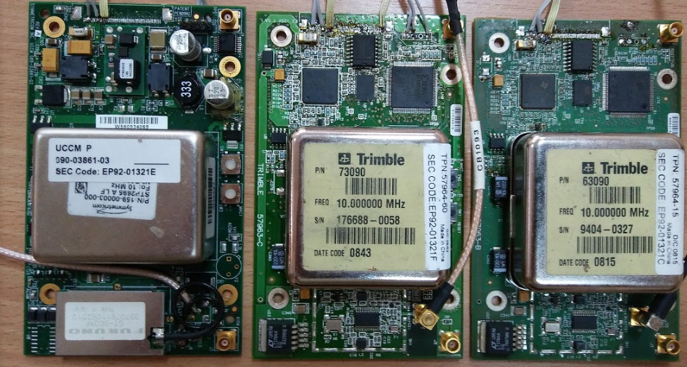 This page describes the pinouts of 50-pin connector, avaliable at "Trimble 57963-C" and "Symmetricom UCCM 089-03861-02" boards, which can be bought on Ebay. They have no direct NMEA support, but have own binary protocol and additional signals, that avaliable on this connector. This receivers are used for DAB SFN operation as alternative for Ublox-LEA-M8F. The main reason of this work - is to receive UTC time from it and get the flags to find that receiver is ready to provide stable 10MHz and 1PPS signals.

Pinouts description
Based on oscillograms and info from [2]. All yellow-marked pins on image - are ground. So, counting from triangle keyed pin (from left to right):
1 --- GND
2 --- UART4 TX (sending actual timestamp each second) is a high-speed serial port. (baud rate: 625000??). Voltage: 3.3V TTL. Transfer starts exactly on rising edge of 1PPS pulse. More info below.
3 --- GND
4 --- ???
5 --- GND
6 --- ???
7 --- GND
8 --- ???
9 --- GND
10 -- ???
11 -- GND
12 -- ???
13 -- ???
14 -- ???
15 -- ???
16 -- ???
17 -- GND
18 -- NC
19 -- NC
20 -- GND
21 -- PP2S pulse (inverted). Pulse length = 100ns. Voltage: 3.3V TTL
22 -- GND
23 -- 10MHz output (GPS locked). Square form.
24 -- GND
25 -- ???
26 -- GND
27 -- ???
28 -- GND
29 -- ???
30 -- GND
31 -- ???
32 -- GND
33 -- UART2 RxD HIGH VOLTAGE, ready for COM-port!
34 -- UART2 TxD HIGH VOLTAGE, ready for COM-port!
35 -- GND
36 -- UART3/Debug RxD ??? Voltage: 3.3V TTL
37 -- UART3/Debug TxD (57600 8N1) binary protocol, each 2 seconds bytes that seen as on "TOD EN" command are sent using this port. Voltage: 3.3V TTL. Transfer starts 70ms after PPS pulse. It's duration is 8ms.
38 -- GND
39 -- ???
40 -- GND
41 -- GND
42 -- GND
43 -- NC on Symmetricom, 3.3V output - on Trimble (10k to GND). This might be input voltage switching control to choose 5.5V or 5.0V.
44 -- +5V input for Symmetricom (5.5V for Trimble)
45 -- +5V input for Symmetricom (5.5V for Trimble)
46 -- +5V input for Symmetricom (5.5V for Trimble)
47 -- +5V input for Symmetricom (5.5V for Trimble)
48 -- +5V input for Symmetricom (5.5V for Trimble)
49 -- +5V input for Symmetricom (5.5V for Trimble)
50 -- +5V input for Symmetricom (5.5V for Trimble)
Here is info about debug protocol avaliable on UART3 port
Bold-marked are flags, that changes depending on state of receiver. The "ready to use" 1PPS and 10MHz signals - is when we have "62 04 85 40"
Symmetricom UCCM logs (found leap sec):
HH*HH -- -- -- -- -- -- -- -- -- -- -- -- -- -- -- -- -- -- -- -- -- -- -- -- -- TT*TT*TT*TT -- SS FL*FL*FL*FL -- -- -- -- -- -- HH
1). no leap sec:
C5 00 80 00 00 00 00 28 1C 52 00 00 20 60 C1 91 00 00 00 00 00 00 00 00 00 00 00 00 00 02 B8 00 00 41 00 8F 50 00 00 00 00 56 8B CA
1a). No leap sec, but have time:
c5 00 80 00 00 00 00 28 1c 52 00 00 20 60 c1 91 00 00 00 00 00 00 00 00 00 00 00 44 d9 b8 7c 00 00 41 00 8f 40 00 00 00 00 22 35 ca
2). got leap sec:
C5 00 80 00 00 00 00 28 1C 52 00 00 20 60 C1 91 00 00 00 00 00 00 00 00 00 00 00 00 00 02 BA 00 11 43 00 8F 50 00 00 00 00 34 DF CA
3). got timestamp
C5 00 80 00 00 00 00 28 1C 52 00 00 20 60 C1 91 00 00 00 00 00 00 00 00 00 00 00 44 D9 AF 6A 00 11 43 04 85 40 00 00 00 00 0F 83 CA
4a). Status OK, but not found leap sec:
c5 00 80 00 00 00 00 28 1c 52 00 00 20 60 c1 91 00 00 00 00 00 00 00 00 00 00 00 44 d9 b8 d2 00 00 60 04 85 40 00 00 00 00 38 16 ca
4b). Status OK, leap sec found:
c5 00 80 00 00 00 00 28 1c 52 00 00 20 60 c1 91 00 00 00 00 00 00 00 00 00 00 00 44 d9 b9 80 00 11 62 04 85 40 00 00 00 00 19 f6 ca
4). synced, ready to work:
C5 00 80 00 00 00 00 28 1C 52 00 00 20 60 C1 91 00 00 00 00 00 00 00 00 00 00 00 44 D9 AF 70 00 11 62 04 85 40 00 00 00 00 A6 EE CA
5). No antenna connected, no signal:
c5 00 80 00 00 00 00 28 1c 52 00 00 20 60 c1 91 00 00 00 00 00 00 00 00 00 00 00 44 d9 b9 b8 00 11 62 04 8f 60 00 00 00 00 3d 55 ca
5). Antenna connected, no signal:
c5 00 80 00 00 00 00 28 1c 52 00 00 20 60 c1 91 00 00 00 00 00 00 00 00 00 00 00 44 d9 b9 be 00 11 62 04 8f 50 00 00 00 00 70 ee ca
5). Antenna connected, locked:
c5 00 80 00 00 00 00 28 1c 52 00 00 20 60 c1 91 00 00 00 00 00 00 00 00 00 00 00 44 d9 b9 ce 00 11 62 04 8f 40 00 00 00 00 3d dd ca
6). Synced, acquistion finalized:
C5 00 80 00 00 00 00 28 1C 52 00 00 20 60 C1 91 00 00 00 00 00 00 00 00 00 00 00 44 D9 E9 1E 00 11 62 04 85 40 00 00 00 00 0C F0 CA
Antenna connected:
C5 00 80 00 00 00 00 28 1C 52 00 00 20 60 C1 91 00 00 00 00 00 00 00 00 00 00 00 44 D8 CC BE 00 11 62 04 45 80 00 00 00 00 2D 05 CA
Antenna DIS-connected:
C5 00 80 00 00 00 00 28 1C 52 00 00 20 60 C1 91 00 00 00 00 00 00 00 00 00 00 00 44 D8 CC D6 00 11 62 04 4F 90 00 00 00 00 A2 32 CA
Antenna connected, ready to work:
C5 00 80 00 00 00 00 28 1C 52 00 00 20 60 C1 91 00 00 00 00 00 00 00 00 00 00 00 44 D8 CC DC 00 11 62 04 45 80 00 00 00 00 6D B7 CA
cold-up:
C5 00 80 00 00 00 00 28 1C 52 00 00 20 60 C1 91 00 00 00 00 00 00 00 00 00 00 00 44 DB 24 14 00 00 41 00 4F 90 00 00 00 00 4F A6 CA
low-voltage:
C5 00 80 00 00 00 00 28 1C 52 00 00 20 60 C1 91 00 00 00 00 00 00 00 00 00 00 00 24 EA 00 18 00 00 41 02 4F 90 00 00 00 00 08 78 CA
hot-up:
C5 00 80 00 00 00 00 28 1C 52 00 00 20 60 C1 91 00 00 00 00 00 00 00 00 00 00 00 44 DB 25 40 00 00 41 04 4F 80 00 00 00 00 61 36 CA
After long running (warmed-up?), led starts blinking.
C5 00 80 00 00 00 00 28 1C 52 00 00 20 60 C1 91 00 00 00 00 00 00 00 00 00 00 00 44 DB 31 9E 00 11 43 04 4F 80 00 00 00 00 7A A2 CA
HH - is start/stop sync header/flag.
TT - is 32 bit timestamp, GPS atomic time started at 06 Jan 1980 00:00:00.
SS - leap seconds offset to UTC.
FL - status flags. See description below.
Status flags description
Based on this debug info and experiments, here is flags that avaliable on this receivers:
FL[0]:
bit6 - always 1
bit5 - GPS oscillator locked (sats are seen at least once)
bit1 - leap second announcement flag (will be added in next end of current half year: at 30 June or 31 December) proof1, proof2
bit0 - setted to 1 when no initial lock to satellites (not warmed)
FL[1]:
bit3 - setted to 1 on trimble when initialized and no sats seen.
bit2 - have GPS time
bit1 - have too small input voltage
FL[2]:
bit7 - 1 on symmetricom
bit6 - 1 on trimble
bit3 - no sync to GPS satellites (setted to 1 if survey not yet finished)
bit2 - always 1
bit1 - no sync to GPS satellites (setted to 1 if survey not yet finished)
bit0 - always 1
FL[3]:
bit7 - 1 on trimble
bit6 - 1 on symmetricom
bit5 - no antenna connected
bit4 - no GPS signal
Flags FL[0...3] value of normal condition - are 62 04 85 40 - for symmetricom and 62 04 45 80 - for trimble. Based on this info, it's possible to implement timestamp reader on FPGA that will set wall clock for EasyDABv2, needed for SFN operation.
UART4 port diagrams
This port start transfer exactly on rising edge of 1PPS pulse. First bit - is start transmission, next - is LSB....MSB and there is also 1-bits signal of END of transmission. Each bit duration - is 1,6uS. Whole a transfer including startbit - is 65 bits, transfer duration- is 104uS.
So, bauds at the first picture would be:
1|00010|10110|00110|10110|11110|01000|10110|00010|00100|00011|11001|00000|0001
Start bit removed 8-byte aligned:
00010101|10001101|01101111|00100010|11000010|00100000|11110010|00000001
Bit reversed result (MSB-to-LSB):
10101000|10110001|11110110|01000100|01000011|00000100|01001111|10000000
Result in bytes:
TT*TT*TT*TT-FL*FL*FL*FL
A8 B1 F6 44 43 04 4F 80
Interpretation:
TT = A8 B1 F6 44 - is LSB-MSB form, or: 44 F6 B1 A8 (decimal: 1157018024 or: Sep 04, 2016 09:53:27 UTC)- is GPS time in seconds, started 6 Jan 1980. Without leap seconds.
FL = 43 04 4F 80 - is receiver's flags, equal to FL[0]...FL[3] of UART3 debug port.
The second window will show beginning of GPS time: 44 DB 13 64 (equal to Aug 14, 2016 11:06:59 UTC).
The big con of this port - is that leap second is not avaliable here.
The big pro - is that start bit is fully synchronized with 1PPS pulse, and this port (actually it's start bit) - can be used as 1PPS pulse as well.
Links:
[1] Hi-res image is borrowed from forum user NivagSwerdna.
[2] EEVBlog forum thread.