
Introduction
This is step-by-step instruction on how to run EasyDABv2 board in SFN mode by using GPS-locked oscillator. Updated 05.08.2017
Supported GPS-receivers:
- Ublox LEA-M8F - small and stable frequency reference with all needed signalling.
- Trimble/Symmetricom UCCM boards, avaliable on ebay. More info about them on blog page.
- Other GPS-receivers are also acceptable if they able to produce one of such frequencies: 10MHz, 24.576MHz or 30.72MHz. And they supports NMEA with GPRMC/GNRMC messages. Baud-rate must be 9600 or 57600 bps.
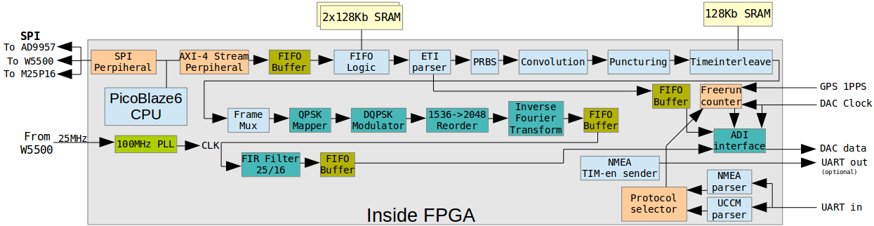
The schematical views of FPGA internals and connection schematic is presented on images below:
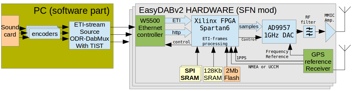
Modification consists of 4 parts:
- Removing DAC's 24.576MHz oscillator and it's load capacitors from the board, and routing external GPS-locked oscillator's signal there.
- Adding two SPI-SRAM buffer chips: 2 x 23LC1024I/SN. This will add 256 kilobytes of buffer to the board. It will be used to pre-buffer input ETI-stream and keep ETI-frames there until it's time to broadcast them on-air.
- Adding GPS-receiver's 1PPS and NMEA outputs to allow board track current time and compare it with ETI-time (in TIST and NASC fields of frame).
- Updating firmware and enabling new features.
Part 1: Frequency reference connection
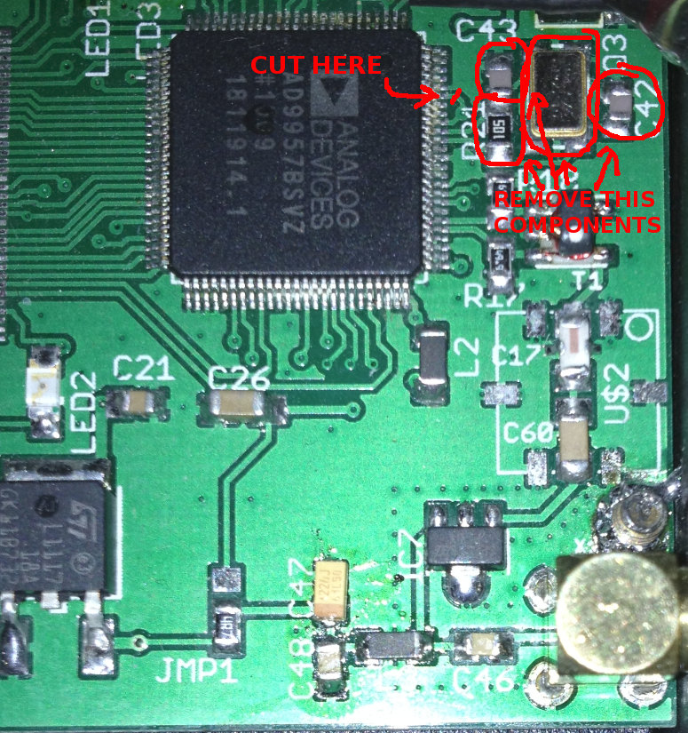
The main modification - is to remove quartz resonator replace 2 capacitors, cut one trace and connect DAC's pin to ground.
Removing quartz is best to do by hot-air station. If You don't have such, just go to closest mobile phone repair and they will do it for you.
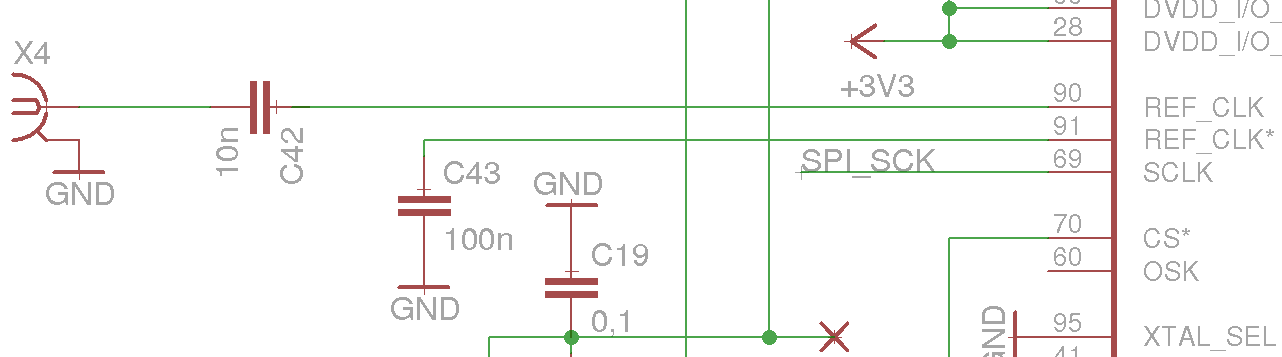
| Original EasyDABv2 part of schematic, related to DAC-crystal quartz: | Modified variant for external clock: |
|---|---|
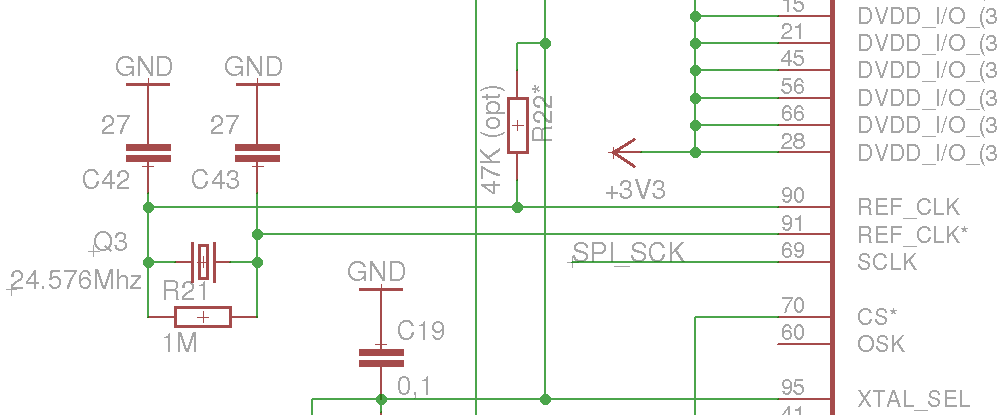 |
 |
 |
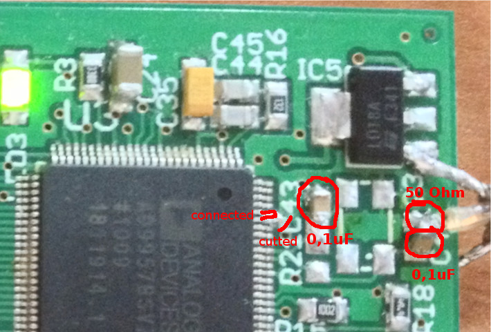 |
So, XTAL_SEL pin must be cutted from VCC and grounded, this needed to switch DAC to external reference mode. The external GPS reference clock - is passed to pin 90 of the DAC over blocking capacitor. If Your GPS receiver needs impedance matching, You also may add 50 Ohm load. Please follow Your receiver's documentation to findout that. If You don't know - just don't add that resistor. DO NOT install 50 Ohm load for Ublox LEA-M8F!
Parts 2 and 3: SPI-RAM installation, NMEA and 1PPS connection by using addon board:
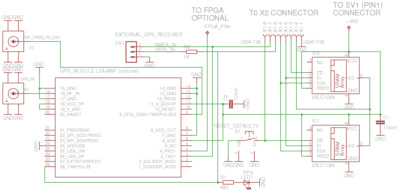
Here is schematic and single-layer PCB of additional components, that using connection to X2 port to enable additional buffering and wiring optional LEA-M8F GPS-receiver:
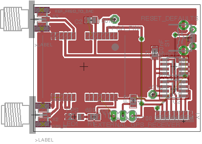
Schematic and PCB in Eagle format can be downloaded here: w5500-lx9-ad9957_sfn_addon.tar.gz
There is also "Hardware reset" button. It's working as "reset board to default IP-address". If it would be pushed during first 5 seconds after powering-up, the board will have IP: 192.168.1.2 netmask 255.255.255.0
If LEA-M8F module is not used, just install SRAM buffer IC's and use "EXTERNAL GPS RECEIVER port", avaliable on this board. You need to connect:
- Addon's X1 port to EasyDABv2's X2 port.
- Addon's "+3.3V" pad to pin 1 of EasyDABv2's SV1 port.
- (optional) Addon's "FPGA_PIN1" pad to EasyDABv2's Xilinx Spartan6 pin1. Needed only if UBlox LEA-M8F GPS receiver's feature "Enable TX only if oscillator is GPS-synced" is needed.
Please note that logical levels must be 3.3V. On this board - only external 1 PPS input - is 5V tolerant. Higher voltage - will burn your board!
Part 2 (alternative): SRAM installation for 2XX boards series, directly to the board:
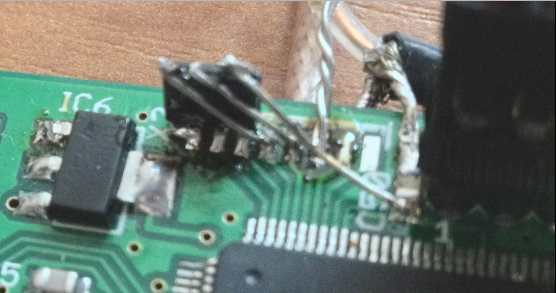
If You are good in soldering, and don't need beauty, You can even solder those SRAM chips on top of X2 connector. The resulting "on-top" image would be like this:
Part 2 (alternative): SRAM installation for 3XX boards series and newer, to special place for them:
This information is for newer boards, where place for SRAM has been routed on PCB. If You have board with 3XX or upper number, take a look at it's back side, if You have place for IC9, IC8 and R22 - then You can install SRAM chips directly to the board:
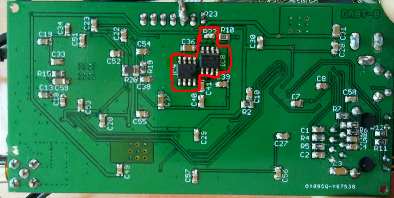
R22 - is wire jumper, connect it's pad's or solder resistor with 1KOhm or less. That's how You inform FPGA that there is on-board SPI-SRAM. (Don't connect R22 pads if You are using SPI-SRAM that connected to X2 pins or on external addon board).
Part 4: SFN Firmware update
So, after doing modification, it's time to enable new firmware, that allows to use external buffer and GPS-receiver.
Source-code archive: easydabv2_sfn-10.10.2016.tar.gz (vendor-provided IP-cores must be regenerated).
Bin and HEX-files for programming clean SPI-flash chip: easydabv2.8_SFN_firmware-05.01.2017_binhex.tar.gz (ip-address will be 192.168.2.4 netmask 255.255.255.0, login-password pair: admin:admin).
HTTP-based update file: easydabv2.8_SFN_firmware-05.01.2017.tar.gz
HTTP-based firmware update procedure description (can be unstable, you need to have backup way to flash the board like JTAG or spi-flash programmer!):
- Download new firmware, extract it and run update script, where setted correctly device's IP-address and credentials:
wget http://tipok.org.ua/downloads/hardware/DAB-TX/Spartan6-FPGA/EasyDABv2/SFN/firmware/easydabv2.8_SFN_firmware-05.01.2017.tar.gz
tar -xvzf easydabv2.8_SFN_firmware-05.01.2017.tar.gz
cd easydabv2.8_SFN_firmware-05.01.2017
gedit update_firmware2.sh
# Edit this shell-script, set proper device target IP and login-password pair for HTTP access.
./update_firmware2.sh
- Wait 8-16 minutes for update been finished. You will see some segments which has been updated during this operation.
- After update been done re-start device by pressing RESET button between power jack and ethernet connector.
- Log-in to the board and reset all parameters to defaults by pressing [set_defaults] button.
- Edit your board's IP address, output frequency and amplitude and source oscillator's frequency (by default it's 24.576MHz), and so-on.
- Apply changes to the board.
Latest firmware features ChangeLog - is presented below:
ChangeLog:
05.08.2017:
- Dropped 10MHz reference frequency support. Use 12.288/19.2/24.576/30.72 MHz.
- Dropped UCCM protocol. Only NMEA with 9600bps is supported.
- Added PWM output as control for internal non-professional GPSDO.
- Added VC-TCXO to Schematic/PCB.
- Added UBlox NEO-M8N to Schematic/PCB.
- Merged SFN-enabled firmware with regular board.
- More info on EasyDABv2 page.
- Added 19.2MHz as supported reference frequency.
- Decreased DMA size for W5500->BRAM-FIFO to 1024 bytes.
- Decreased SPI-FIFO block size to 512 bytes. This change decreases data transfer granularity and enchances ETI-stream network stability.
- Implemented WatchDog feature: if there is no output during 40 seconds, then modulation logic and FIFO's will be resetted. This feature enables fast re-sycnhronisation after network disconnection.
- Implemented DMA feature for W5500->BRAM-FIFO flow. This fixes "bottleneck" in CPU, so from now even internet-stream can be used as source for boards without SPI-buffer (interenet must be latency-free, 10ms is ok).
- Decreased TCP RTR timeout to 100ms. This will enchance buffering.
- Enabled TCP Keep-Alive packet sending if connection is stucked. If no reply, then reconnect in 4 tries.
- Enabled CRC checking of ETI-frames, and if it doesn't match, transmitter will re-sync.
Web-UI new features:
When firmware been updated, the board will still be avaliable on previously configured IP-address. But You will need to apply changes (new config) to the board at least once. There will also be new "processing"-related options:
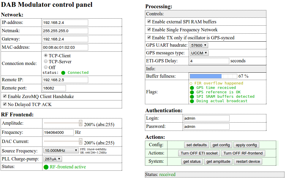 |
Help info Networking This section is responsible for configuring network parameters, such as IP-address, netmask, gateway,etc. Also stream source settings must be setted here, like board's role: TCP-server or client, ports to losten or to connect and additional flags as basic ZeroMQ protocol handshake, that enables ZeroMQ communication with ODR-DabMUX software. Setting TCP no delayed ACKnowledgement is needed in low-performance networks, where packets may be lost. RF-Frontend This section can configure output DAC parameters, like output signal's frequency and it's power. The power is setted as percentage value of output amplitude and output DAC current. If You need low-noise output, then don't increase amplitude and current hugher than 100%, because this will bring more noisy (but higher power) signal. Also this section allows to choose input source frequency of crystal oscillator or external generator. Processing This section - is for additional processing flags and statuses. Here You can enable additinal hardware SPI SRAM buffer, based on 2 chips of 23LC1024, that allows to buffer more than 1 second of data. Also here You can enable Single Frequency Network (SFN) mode, which needs additional GPS receiver like Trimble/Symmetricom UCCM or Ublox LEA-M8F module. Additional UART and 1PPS pins must be connected to the board, from which high precision time will be received by the board. You can choose GPS receiver's module type and UART baud rate here. Authentication In this section this web-page access can be limited by your credenntials. Default - is admin:admin. Actions Here You can make actual actions with the board. After editing some parameters you must push [apply config] button to apply Your changes to the board. Also You can re-read board's status by pushing [get status] and re-read internally saved config from the board by pushing [read config]. Button [set defaults] will set safe parameters to the board's config that can be applied later. You can enable or disable transmission on-the-fly by pressing [Turn On/Off RF frontend] without need to press apply button. Also You can disable/enable ETI-stream connection to the signal's source by pressing [Turn ON/OFF ETI socket] button. Resetting the board If You forgot password or some settings are wrongly saved, You can reset board by connect wire jumper between first and last pins of X2 connector (pin 1 and pin 8) before power-up the board. |
More detailed description of processing section:
Enable external SPI RAM buffers - is option that enables usage of this buffer (if it's ofcource soldered correctly). In regular (non-SFN) mode - this buffer works as network latency compenstaion buffer. It's simply pre-fills up to 75% and then starts broadcasting. So network latency fluctuations will be compelsated by this buffer. In SFN mode - this buffer, and it's fullness will represent amount of ETI-frames that waiting in queue to be processed. If it's very small, like less than 15% - this means that You can increase ETI-GPS delay to have more frames expecting in queue and compensate network latency. If this buffer is too high, like more than 90% - this means that ETI-GPS delay is too big, and board's processing of ETI-frames can stuck just because buffer overflow.
Enable TX only if oscillator is GPS-synced - is option where board will transmit signal only if GPS satellites are seen on the sky and it's reference oscillator - is locked to them. This option enables reading additional flags from GPS-receiver to check lock state.
When Ublox LEA-M8F receiver is used, then additional wire must be connected between GPS-addon board and EasyDABv2: connect FPGA's pin 1 to the pad with same name on addon board. This way EasyDABv2 will send UART-commant that enables sending UBX-TIM-TOS messages by UART output.
This option also avaliable for debug-protocol on Trimble/Symmetricom UCCM receivers. For generic NMEA signals - this option is not avaliable, since NMEA protocol itselve - don't sending any oscillator-locking info.
Not that if this option is selected and GPS-antenna is not installed on "clear sky", with at least 140° of the sky without walls/etc. then there is a chance that in some time GPS satellites will not be seen and the board will not broadcast any data until this condition ends.
GPS Message type - selects which protocol is used by GPS receiver:
- NMEA - use it with LEA-M8F and other generic NMEA receiver.
- UCCM - use it with Trimble/Symmetricom UCCM receivers. You need to connect ground pad and 3.3V UART output, located on receiver's pin 37 of 50-pins header (UART3/Debug TxD). More info about pinouts of this type of receivers - on blog page.
ETI-GPS delay - number of seconds of difference between GPS time and ETI-time. The step is 156.25ns. Minimal value - is 0s Maximum - is 15.999s. This parameter must be experimentally chosen for stable broadcasting. Basical pre-calculation will looks like:
Tbuff = ( 2097152 / Ebr ) - 1.25
Where:
Tbuff - is maximal buffer time that can be setted to prevent overflows.
Ebr - ETI-stream total (summary) bitrate. It's calculated as sum of bitrates of all announced (avaliable) stations.
Few samples:
Single 128kbps station: 2097152 / (128000) - 1.25 = 15.134s. If calculated number - is bigger, then max can be used: 15.999s, and board will have 15.999 seconds delayed stream.
Six stations of 128kbps streams: 2097152 ∕ (128000 * 6) - 1.25 = 1.48s. Maximal buffered amount of seconds - is 1.48. That's still enought to make stable connection to the ODR-DabMUX over intenet.
This calculation also depends on how correctly is setted time on multiplexor's PC and also it depends on network latency. IT's recommended to start from low value and increase it up to 80% of buffer fillness. If board's amplitude setted to 128 (100%) and another board have different value, note that first board will send signal few cycles earlier due internal amplitude scale scheme will be passed thru and inside AD9957 there is less cycles needed to process data.
Changing Transmission power on-the-fly
This firmware also presents new feature: changing transmission power without saving it to start-up configuration. This option - is useful if You need to change transmission level immediatly, without restart of the board. This power change will not saved. After restart, board starts with amplitude value, that has been previously saved to internal flash memory.
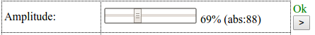 |
<--- To do this, just change the level of the "Amplitude value" and push [>] button that will appear the left of tracking wheel.
|
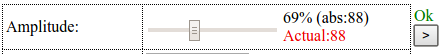 |
<--- After pushing it, You will see that there is red text with "Actual value" - this is real value of transmission amplitude.
|
|
<--- If You don't know it's value, it can be updated by pressing [get_amplitude] button in Actions->System section.
|
Measuring tools
For checking, that transmitters are in-sync, there is very nice application, called odr-dab-cir. It's showing delay between transmitters by calculating phase referense symbol's "fingerprint" on the air. Some measuremet results by using this app can be found on SFN report page. Also to see constellation map, there is gr-dab graph that able to show it.
New firmware will change function of LED1. Now it will flash with NULL symbol interval (once per 96ms). You can even use oscilloscope to see how SFN is synced, since this LED's must blink on different SFN-enabled devices at the same time.
Known issues
- This firmware is not yet productuion-ready! On R&S ETL analyer the signal becames unstable for some period of time, this may even burn Your amplifier. This bug will be fixed as soon as possible.
- Device is still network-latency dependant. It's highly recommended to use wired network and have smallest possible latency. Anyway my test environment proves, that if ODR-DabMUX server that located in Germany and EasyDABv2 that located in Ukraine - such environment is working fine without issues. The "pings" latency this way - is less than 50ms for 1460-bytes packets. With higher latency You need to decrease ETI-stream summary bitrate by removing stations or by lowering they bitrates.
- If buffer usage is around 95-100%, then web-ui can be less responsive and there is a chance that it can stuck. It's good to disconnect board from eti-stream source and decrease ETI-GPS delay to make lower percentage of buffer usage.
- After low-delay network stucking, it's possible that re-synchronisation in SFN-mode will take much time. Because all late-received will be processed as usual one's and will be dropped only at the last block. And this block dropping packets only with 2x of regular packett flow speed. Sometimes 2x speed - is not enought for fast re-synchronisation.