
Introduction
This page describes hardware for Ethernet-based DAB transmitter (EasyDABv2). Last update: 02.03.2018
- Nominal Transmit Frequency: 176 ... 239 Mhz.
- Maximal Tramsmit Frequency: 400 MHz (with 1Ghz reference clock).
- Transmit Power: -60 ... 15 dBm.
- Signal shoulders height: 54 dB (if TX power is 3 dBm).
- Drivers Installation Needed: NO
- Software Needed: NO (Only if you need to create ETI-stream yourselve, ODR-DabMUX is needed)
- LEDs That shows state: Yes (underflow, PLL-lock, link activity, fpga status)
- I/Q samples width: 18 bit
- Complex sample rate: 6144 kS/s.
- Input interface: 10/100 Mbit Ethernet
- External power: 5V 2A (power consumption - is up to 700mA in old PCB versions, and up to 450mA in new one's)
- Output RF connector: SMA-Female
The main point of creating this hardware - is to have possibility to create DAB stream without need of PC. So all CPU-intensive job, like: ETI-processing, Adding error correction codes, Adding Phase Reference, DQPSK, Fourier transform/COFDM and I/Q processing has been moved from the software to hardware part (into XC6SLX9 FPGA). After this changes been done, all what is needed - is ETI stream from the satellite provider or from ODR-DabMux sent by the TCP-connection to the board. Just set network parameters, point to the source of ETI-stream (ip and port), and set RF frequency and amplitude - and volia! There is also modifications page, that describes how to enables SFN operationing by using various GPS
Hardware Description
The software-hardware solution looks like this:
.png)
Additional processing done inside FPGA (actual modulator schematic):
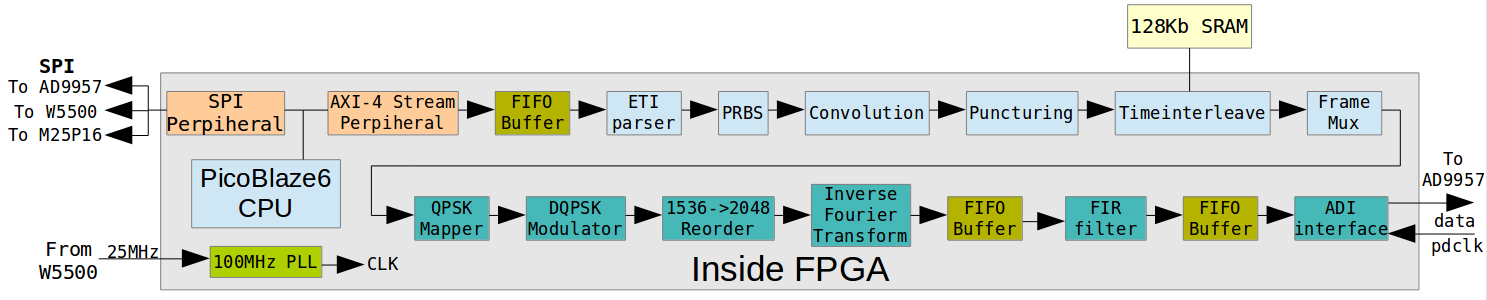
Here is the list of used or created IP-cores which does the job inside FPGA:
- PicoBlaze6 CPU + SPI and AXI4-Stream perpiherals (used as arbiter for datastreams and configurator of the DAC).
- FIFO Buffer for ETI-frames
- ETI-Parser (this block parse ETI-NI stream and prepare it for modulator)
- PRBS - mix phase reference with data
- Convolution - adds error correction code to the datastream
- Puncturing - puncture convoluted data depending on choosed error protection level.
- Timeinterleave - this block interleaves data in time, as described on specification. It needs additional hardware SRAM, which is presented on the board, since it's max size may be up to ~1Mbit for 64 stations.
- Framemux - mixes 4 ETI frames into single frame (for DAB Mode I) needed by radio interface.
- QPSK Mapper + frequency interleaver (IP Name: map_
interleave_1_0) - DQPSK Modulator. (IP Name: dqpsk_
modulator_1_0) - 1536->2048 frequency reorder block. (IP Name: pre_ifft_
reord_1_0) - Inverse FFT (xilinx default), with cyclic prefix insertion and auto-controlling of dynamic range.
- FIR filter, which increases samplerate up to 8192 kSamp/sec and rejects unneeded frequencies.
- FIFO Buffer for complex samples
Additionally, each FIC data on ETI-header is parsed on-the-fly. This means, that you can switch on-the-fly from one source to another without rebooting or reconfiguring anything. The limitations are only transmission mode will always be 1 (1536 carriers), and frame alignment must be met (no interruption in the middle of the frame during transmission).
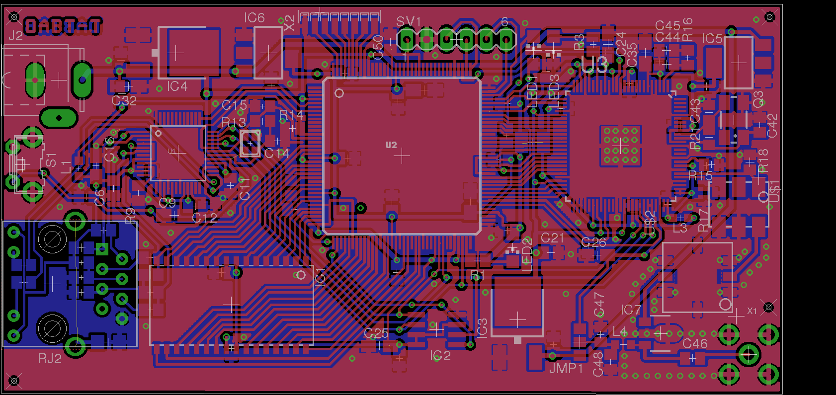
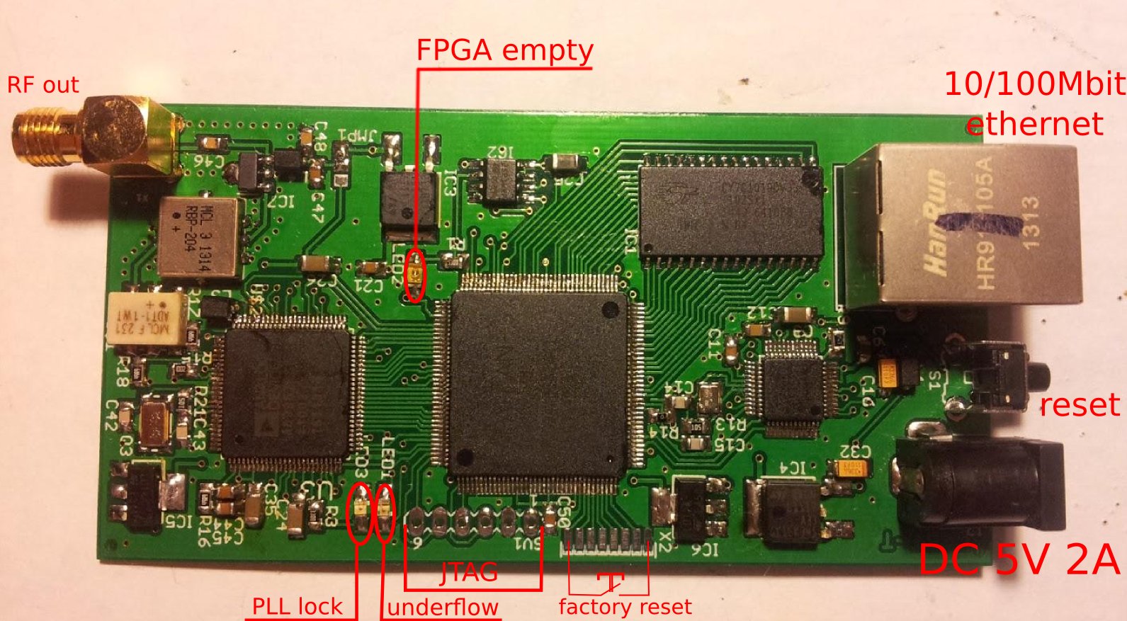
Schematic and PCB
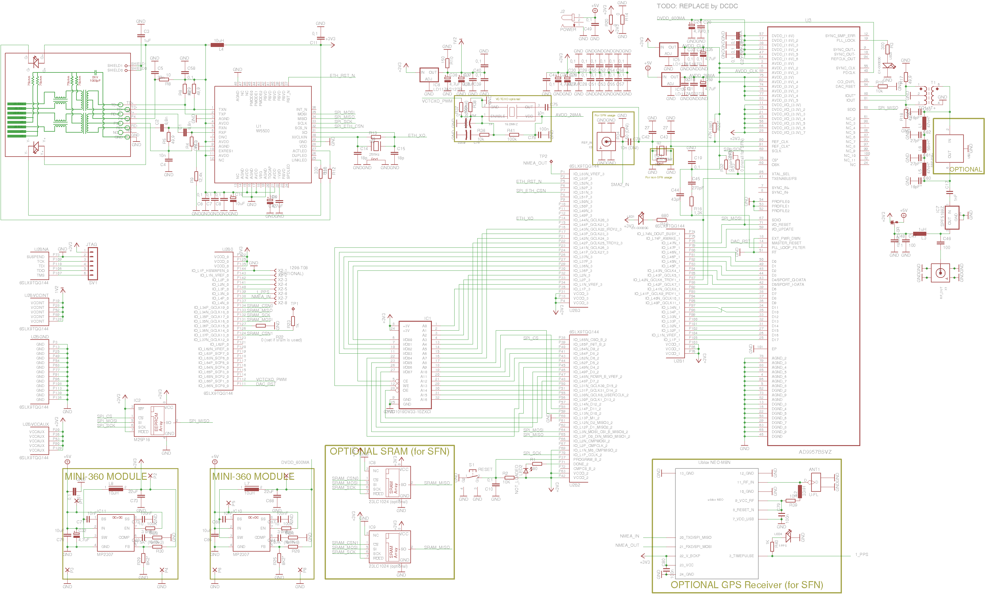
- Wiznet W5500 - ethernet module, which does TCP/IP job. Maximal bitrate for 50MHz SPI bus - is 16Mbit/s.
- Xilinx XC6SLX9 - FPGA with 8-bit soft-cpu and all modulation blocks for DAB mode I.
- Cypress CY7C1019DV33 - SRAM for timeinterleaver block inside FPGA, supported up to 64 stations.
- Analog AD9957 - DAC which used in previous designs.
- Micron M25P16 - Flash for FPGA bitstream, webpages and saved RF-configuration.
- RFMD SPF5189Z or SPF5122Z - low-noise MMIC amplifier.
- capacitors, resistors, LDO's, crystal's and RF-filter.
Eagle project files are in source code section.
Software and other tools
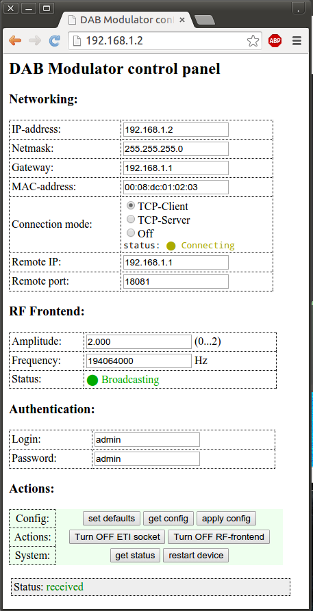
Configuring is based on web-interface on port 80 of the device's IP:
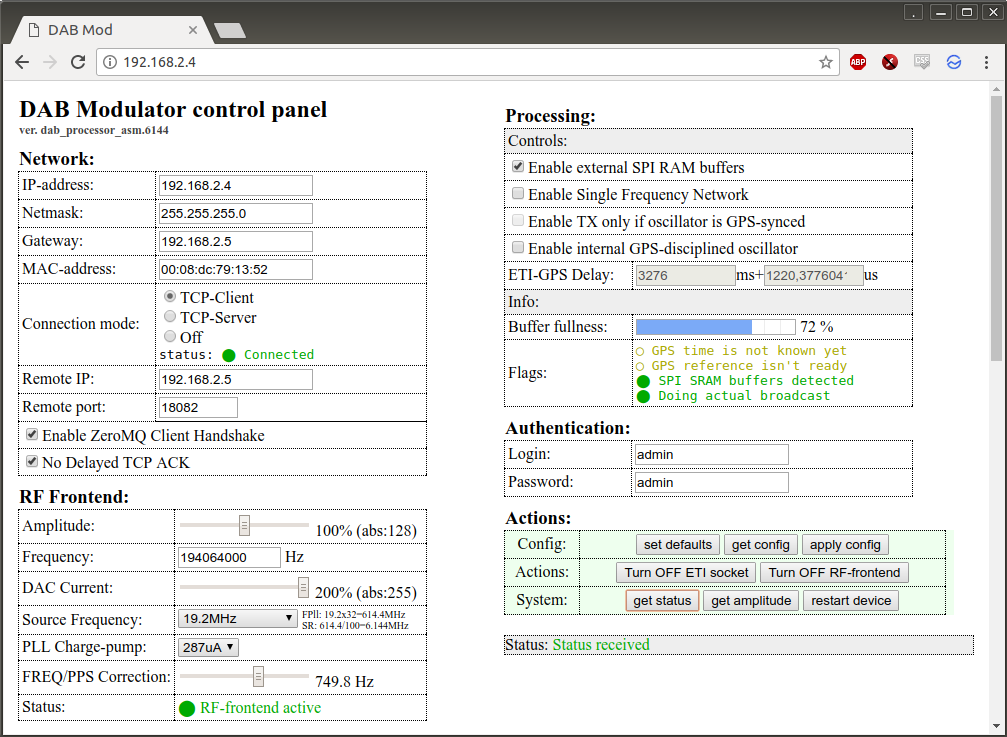
Older non-SFN enabled firmware's web interface's sample is here.
As additional features, You can turn ON/OFF transmission on-the-fly by pushing [Turn OFF/ON RF-frontend], this will switch DAC to/from sleep mode, so output signal will appear or disappear immediatly. In this case ETI-frames processing is still working.
Also if you wish to (dis)connect modulator from the server from which it receiving ETI-frames, you can push "Turn OFF/ON ETI socket" and connection to the source will be dropped (or initiaded again).
Usage examples
Modulator needs only network ETI-stream, provided by ODR-DabMux or satellite ETI stream (converted to ETI-NI format), below are some examples on how to produce such stream and feed it to modulator:
Using pre-recorded satellite dump file 0,0x0425.bin.eti:
$ nc -l 0.0.0.0 18081 < 0,0x0425.bin.eti
Using old CRC-Dabmux application:
$ crc-dabmux-0.3.0.4/src/CRC-DabMux -L "LabelTest" -A test_file_48khz_128kbps.mp2 -b 128 -i 1 -S -L "Label1" -C -O tcp://*:18081
Or You can use minimal configuration file minimal.mux and run it to produce ETI-stream:
$ odr-dabmux minimal.mux
Next, go to configuration interface of the board and and set "Connection mode" to "TCP client", "Remote IP" to your computer's IP, where you are running odr-dabmux and "Remote PORT" to "18081" (this port is listened by odr-dabmux for incoming connections. After set them, push [apply config] button and answer "Ok" for reboot the board. That's all, you must see that new client connected to the odr-dabmux, and board's red led ("underflow") must be turned off, and from now you are on the air. Please note, that ZeroMQ password protection - IS NOT SUPPORTED. You need to provide raw TCP for ETI-data or ZeroMQ without password.
You can discuss this device usage and share your experience in mmbtools group in thread about FPGA DAB Modulator.
Measurements
Signal measurements, and process of enchancing of it's quality is described on this page.
Source code
| Old pcb (vesrion 1...3), non-SFN firmware: |
|---|
|
easydabv2.8192-24.02.2016.tar.gz - Xilinx ISE 14.7 archive project with all IP blocks and modules source code. To generate bitstream, open this ISE project and run "Generate Programming File" task. After it successfully completed, you will find "easydabv2_8192.bit" file, which you can use as bitstream for feeding FPGA. w5500-lx9-ad9957_spibuff-10.11.2016.zip - Eagle Schematic and PCB project. Size 10x5 cm. Ready-made firmware for FLASH ic with webpages and saved configuration: easydabv2_8192_full.tar.gz (device's ip:192.168.2.4/255.255.255.0, eti-source's address setted to: 192.168.2.3:18081, channel: 7D, ampitude: 1.3) easydabv2_18.03.2016.tar.gz Below is described how to run this update. |
| New PCB and SFN-enabled firmware: |
|---|
|
easydabv2_sfn-28.11.2016.tar.gz - Xilinx ISE 14.7 archive project with all IP blocks and modules source code. To generate bitstream, open this ISE project and run "Regenerate cores" then "Generate Programming File" task. After it successfully completed, you will find "easydabv2_6144.bit" file, which you can use as bitstream for feeding FPGA. w5500-lx9-ad9957_spibuff-05.08.2017.tar.gz - Eagle Schematic and PCB project. Size 10x5 cm. Ready-made firmware for FLASH ic with webpages and saved configuration: easydabv2.6144-28.11.2017.fullflash.tar.gz(device's ip:192.168.2.4/255.255.255.0, eti-source's address setted to: 192.168.2.5:18082, channel: 7D, ampitude: 100%) Firmware and script for HTTP-based update: easydabv2.6144-28.11.2017.tar.gz DO NOT run HTTP-based firmware update if You don't have backup ways to revert board to working condition, like SPI-flash or JTAG programmer! SPI-Flash can be probrammed on-board (without desoldering). But during probramming the "Reset" button must be kept pressed. |
Additiona notes, related to SFN-enabled firmware
Non-SFN boards also works with newer SFN-enabled firmware. So You can use this firmwares on old boards too (use 24.576MHz as reference clock for old pcb's and 19.2MHz - for new one's). It's also highly recommended to have additional SPI-SRAM's on-board for more stabe streaming on high latency networks.
Note1: if You have no additional SPI-SRAM buffers, then accessing to configuration web-interface is recommended only when ETI-stream source must be turned off, so board is not loaded by modulation task.
Note2: If some parameters has been changed on web-interface and [apply config] has been pressed and the page status stucks at "erasing partition..." and don't want to show "restart device?" dialog, then just change anything on configuration webpage and press [apply config] once more. Otherway You need to do hard reset of the board.
HTTP-based firmware update process
To start firmware update by using network interface, you need good LAN connection to the board (without WiFi). Also it's highly recommended to have PC with LPT port and soldering skills as backup variant if something goes wrong to update firmware directly on FLASH IC M25P16 by using very simple programmer. But first it's good to try http-based firmware update:
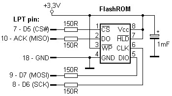
- Unpack archive: tar -xvzf easydabv2_XX.XX.XXXX.tar.gz
- Go into unpacked directory: cd easydabv2_XXXXX
- Edit update_firmware.sh (it's first line) by setting correct deivce's IP and login/password pair.
- run it: ./update_firmware.sh
- Confirm that you want to update by pressing "y".
- Wait for "Update has been finished." line. Update can take up to 16 minutes.
Resulted photo of first prototype PCB and latest factory produced one's
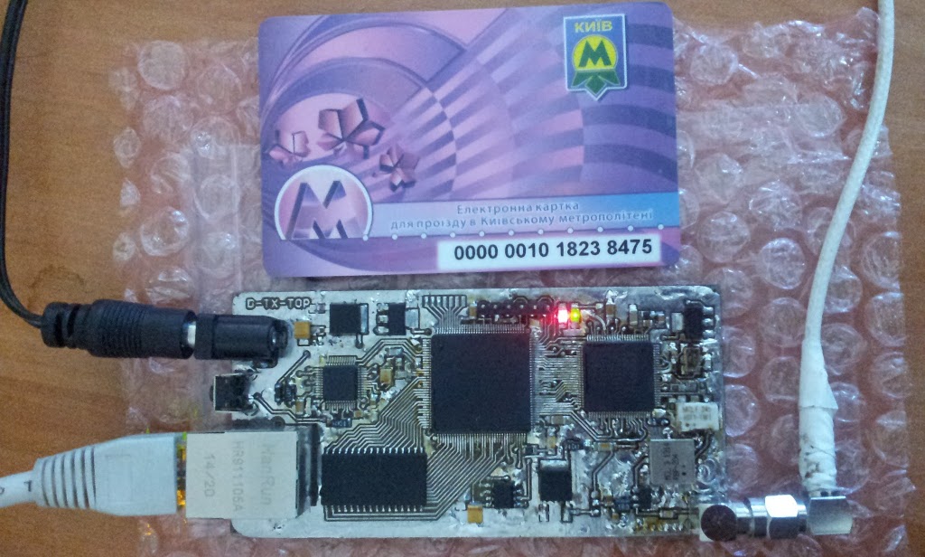
If you have interest to buy tested and configured device, just write me.
Ready to use and tested devices are avaliable for sale. Currently I'm out of stock. The next batch will be avaliabe in February 2019. The price - is 250$ including 10-17 days shipping to Europe, US/CA. For 7-days EMS shipping it will cost additional: +30...40$ (depending on destination). Board does not contains GPS-receiver.
Status LED's description
- Link Connected (yellow) on the ethernet connector.
- Link Active (green) on the ethernet connector.
- LED1 - ETI-stream is not ready (red).
- LED2 - FPGA is not configured (red) at the center of the board.
- LED3 - PLL-locked (green) for DAC.
While normal operationing, link leds and LED3 must be bright (link connected + active + PLL-locked). If you have LED1 bright "ETI-stream is not ready", then board can't find eti stream from provided source.
Resetting device to defaults
If device's IP-address or login-password pair has been forgotten, then hardware reset to factory defaults - is needed. To reset device to factory defaults do this:
- Before resetting, make sure that board's reference clock "Source Frequency" in web-UI - is known. It can be 24.576MHz (if quartz resonator is used) or 19.2MHz (if VC-TCXO is used).
- Turn off power of the board.
- Connect first and last pin of X2 connector's pads by the small wire or use tweezers for example, as shown on this picture. If You have 9 pins on X2, then connect second and last pads of it to do reset.
- Turn on power of the board and wait for 5 seconds.
- Disconnect wires from the pads, which was been connected at X2.
- Now your device have IP 192.168.1.2 and netmask 255.255.255.0, configure your PC to use IP for example 192.168.1.3 and same netmask.
- Open Chrome web browser and go to http://192.168.1.2 (Please use Chrome, since it works fine with js Uint8Array)
- You will see some warning messages about bad MAC, ignore them.
- Push button [set defaults]
- Configure your preffered device's IP address, netmask and gateway by changing it's fields in "Networking" section.
- Configure device's connection mode: client or server (in most cases it's client, who will connect to remote tcp server for receiving ETI-stream from it). Also configure remote server's IP and PORT from which to receive ETI.
- Set correct value of DAC's "Source Frequency", after reset it's setted to 24.576MHz, but if You have TCXO instead of crystal (on all boards shipped after May 2017), You need to set value to 19.2MHz (You can see it's installed on bottom part of the board).
- Set Amplitude and Frequency, in which you would like to transmit, for example:
Amplitude: 1.2
Frequency: 194064000 (this would be 7D channel) - Set login and password for this configuration webpage if you wish.
- Push [apply config]
- Wait for 10 seconds, the alert message "Device Restarted!" will be shown.
- Done, now your modulator back to live and have new configuration.
TODO and Known Issues
EEP_B error correction mode - is buggy for now and it's not properly working. Use UEP or EEP_A modes for error correction.(fixed in 05.08.2017 firmware)The Ethernet network must be latency-free (Do not use WiFi to transfer ETI-stream to the board).(fixed when used external SPI buffer)- Do not enable transmissission without 50 Ohm RF load. It's low-power, but MIMC amplified can be bricked without load.
- When connection is interrupted in the middle of the ETI-frame, sometimes (in very rare case) board may stuck, then reset button may help to make board alive.
During access to configuration webpage, it's possible that board can stuck your network, so for now just configure board once, and try to minimize accessing to config page (it happens if accessing throught WiFi-network, but not happens of etherrnet only used).(fixed in new firmware).- To make clear signal, it's recommended to set "Amplitude" value no more than 1.3 (or 130%), because of higher value produces much more noise on side band (keep shoulders 40dB). Best value - is 1.0. This is actual output power regulator.
- Only DAB Mode I is implemented. There is no nearest plans to enable other modes.
- To make R9 resistor (12,4K 1%): use 2 resistors of 25K 5% in-parallel (pick needed 25,2K values from few of them), or use 6,8K 1% + 5,6 K 1% in serial.
Central wire of primary winding (adi-chip side) must be connected to the ground on schematic (it's already connected on PCB).(fixed on schematic)Accordingthisandthisthreads, to decrease PLL Loop noise, it's filter value must be changed to this ones: For 1,2MHz bandwidth C44=44pF, C45=287pF, R16=1,27K. For 2.2MHz bandwidth: C44=13pF, C45=85pF R16=2,3K(fixed on schematic)C42, C43 must be 27pF for quartz crystal used in this design.(fixed on schematic)- If DAC quartz generation not starting, then additional 47K resistor between AVDD +1.8V and REF_CLK pin - is needed.
It is possible to decrease FPGA resources by disabling gain normalizer and use full precision output after iFFT.(fixed in new firmware)The current DAC samplerate of AD9957 is 516.096 MHz. It is possible to add FIR filter into the block design, so we can bring up DAC samplerate up to 1Ghz.(fixed in new firmware, DAC clock setted to 589.824 MHz to prevent overheating of the board).Addu-blox LEA-M8FGPSDO and try to make SFN network transmission.(added link to modifications page that describes SFN mode)- TODO: add information on how to upload firmware to flash ic by using flashrom app + rayer_spi adapter. Add instructions for updating firmware on linux by network. (There is instructions presented about update procedure, but it's unstable yet).
Error Protection Profiles info
Here is a list of error protection profiles, that is tested with SFN-enabled firmware and works as expected on LG Stylus 2 and unbranded DAB+ receiver:
UEP 1...5: 32 48 56 64 80 96 112 128 160 192 224 256 320 384 Kbps.
EEP_A 1...4: 16 24 32 40 48 56 64 72 80 88 96 112 128 144 160 192 Kbps.
EEP_B 1...4: 32 64 96 128 160 192 Kbps.
Profiles that partially not works on receivers, they are noto supported by standartds, but playable on some receivers:
UEP for: 8, 16, 24, 40 Kbps (not supported by standard, but works on some receivers except level 5 which is not works at all).
UEP-1 for: 56, 112, 320 Kbps (not supported by standard, but works on some receivers).
UEP-3 for: 320 Kbps (not supported by standard).
UEP-2, UEP-4 for: 384 Kbps (not supported by standard).
EEP_A: 8 Kbps (receivers can't decode such stream).
More info about error protection profiles - is at ETSI EN 300 401 page 134.
Changelog:
02.03.2018:
- Found bug where during cold-start (1 second before FPGA loads) the EasyDABv2 board produced wide-band noise on all pass-band spectrum. The hotfix work-around: To pull-down TXENABLE pin of AD9957 by 2.2K resistor to the GND. Schematic and PCB will be updated shortly. More info with images and videos on fixup's page.
28.11.2017:
- Fixed SPI-SRAM issue. Now enabling additional SRAM buffer - works as expected and does buffering.
- Added TII feature: Now EasyDABv2 can be configured to transmit TII information in NULL symbol. Used proper (correct) TII implementation for adjacent frequencies.
- Changed behaviour of LED1: it's blinking 10 times per second as before, but brightness duration decreased from 1.3 ms downto 50 microsecons (activity is still visible in darkness).
- Increased FFT scaling. Now FFT overflow will not happen.
- Comparing to older firmwares, this one adds 1040uS delay in SFN mode. So ETI-GPS delay must be decreased by this value for boards with new firmwares.
05.08.2017:
- Modified PCB and schematic by adding 19.2MHz VC-TCXO oscillator as frequency reference source. It's fine-tune is controlled by PWM signal from FPGA.
- Added functionality of non-professional GPSDO, it's syncing reference clock to 1PPS signal of GPS-receiver.
- Merged SFN-functionality to latest firmware.
- Added special place on bottom of PCB for U-Blox NEO-M8N GPS-receiver (receiver is not included!)
- Fixed bugs in puncturing block. Now EEP_B and UEP-5-48kbps profiles - works as expected.
- Dropped support of 10MHz reference clock and UCCM protocol. Supported NMEA 9600bps and 12.288/19.2/24.576/30.72 MHz as source clock.
- NOTE, there is known issue: when SPI-SRAM is enabled, on some boards there is no signal. Just disable SPI-SRAM usage if You have this problem or wait for bugfix.
10.11.2016:
- Modified PCB by adding DC-DC convertes for digital-related parts. This modification decreases power consumption from 700mA down to 450mA. So now board is less heating.
- Added routes on PCB for optional external reference oscillator input.
28.09.2016:
- Modified PCB for adding optional SPI SRAM buffers for SFN operationing.
- Finalized SFN firmware and modifications list for enabling SFN feature by connecting GPS-receiver - is described on it's own page.
06.06.2016:
- Added modification list for enabling basic version SFN on this board (not full implementation yet). Lab simulation results is described as weell.
18.05.2016:
- Added ZeroMQ input format support. The implementation is very basic and does not support password-protected stream.
- Fixed login-password access to the configuration interface.
- Now firmware consists from 2 parts: main firmware, which does the job and backup firmware, which will be activated in case of faily update. So update now become safer.
- Alternative firmwares to create FM Broadcast transmitter with RDS and internal MP3 player and shoutcast title extraction is described at EasyFM page.
03.03.2016:
- Alternative firmwares to create direct sampling transmitter for Analog-FM and DRM/DRM+ with help of GnuRadio has been created and described at EasyQDUC page.
29.02.2016:
- Boards avaliable for shipping.
26.02.2016:
- PCB: band-pass filter changed to low-pass filter LFCN-225+ (225MHz max frequency). This adds possibility to use board as DRM/DRM+ or Analg-FM transmitter (with future independent firmware that would be avaliable soon).
- PCB: ADT1-1WT+ transformer has been changed to TC1-1T+ (for 50Ω impedance).
24.02.2016:
- New firmware avaliable.
- Fixed flooding on network with high latency when accessing to web interface.
- Removed gain control module to decrease ampliture deviation. NOTE: output power is decreased to 45 mW (PEAK)!
- Added FIR filter to increase samplerate to 8192 kSamp/sec to reject images close to signal.
- Updated source code and ready-made firmware archives.
- Added measurements page, that describes signal quality and location of dead frequencies.
06.01.2016:
- Fixed transformer position on schematic.
- Updated values of C42, C43, C44, C45, R16.
- Decrease non-power via's diameter to 0.3mm.