
Introduciton
This page describes hardware for digital USB DAB transmitter, called EasyDABv1-USB. Take a look also to EasyDABv2-Ethernet modulator too, it don't need PC for modulation.
- Nominal Transmit Frequency: 3 ... 206 Mhz.
- Maximal Tramsmit Frequency: 400 MHz (with 1Ghz reference clock).
- Transmit Power: -60 ... 5 dBm.
- Drivers Installation Needed: Yes
- Software Needed: ODR-tools (multiplexer + part of modulator software)
- LEDs That shows state: Yes (underflow, PLL-lock)
- I/Q samples width: 16 bit
- Complex sample rate: 2048 kS/s.
- External power needed: No
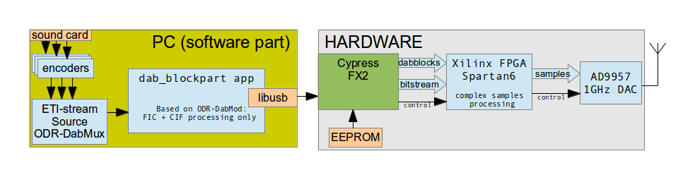
The main point of creating this hardware - is to have possibility to create DAB stream without need of PC. So all CPU-intensive job, like: DQPSK, Fourier transform/COFDM and I/Q processing has been moved from the software to hardware part (into XC6SLX9 FPGA). After this changes been done, the low power ARM CPU with 667MHz have only 10% load of single core, when using this hardware-accelerated signal processing (there is still some ETI-parsing and FIC/CIF pre-processing is doing in software side). The resulted bitstream on USB bus between software and hardware - is about 2.5 MBit/s (previously it was ~70Mbit/s). The boards may be USB-bus powered. And works much more stable comparing with modulator without FPGA, previously desribed here.
Hardware Description
The software-hardware solution looks like this:
Additional processing done inside FPGA (actual modulator schematic):
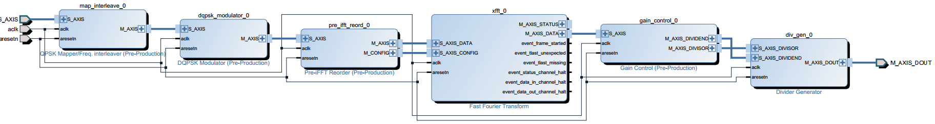
- QPSK Mapper + frequency interleaver (IP Name: map_
interleave_1_0) - DQPSK Modulator. (IP Name: dqpsk_
modulator_1_0) - 1536->2048 frequency reorder block. (IP Name: pre_ifft_
reord_1_0) - Inverse FFT (xilinx default), with cyclic prefix insertion and auto-controlling of dynamic range.
- Gain control (do the same thing as crc-dabmod with argument "-g 1" meaning max possible gain), it finding numenator/denominator that passing to divider IP module next after it. (gain_control_
1_0)
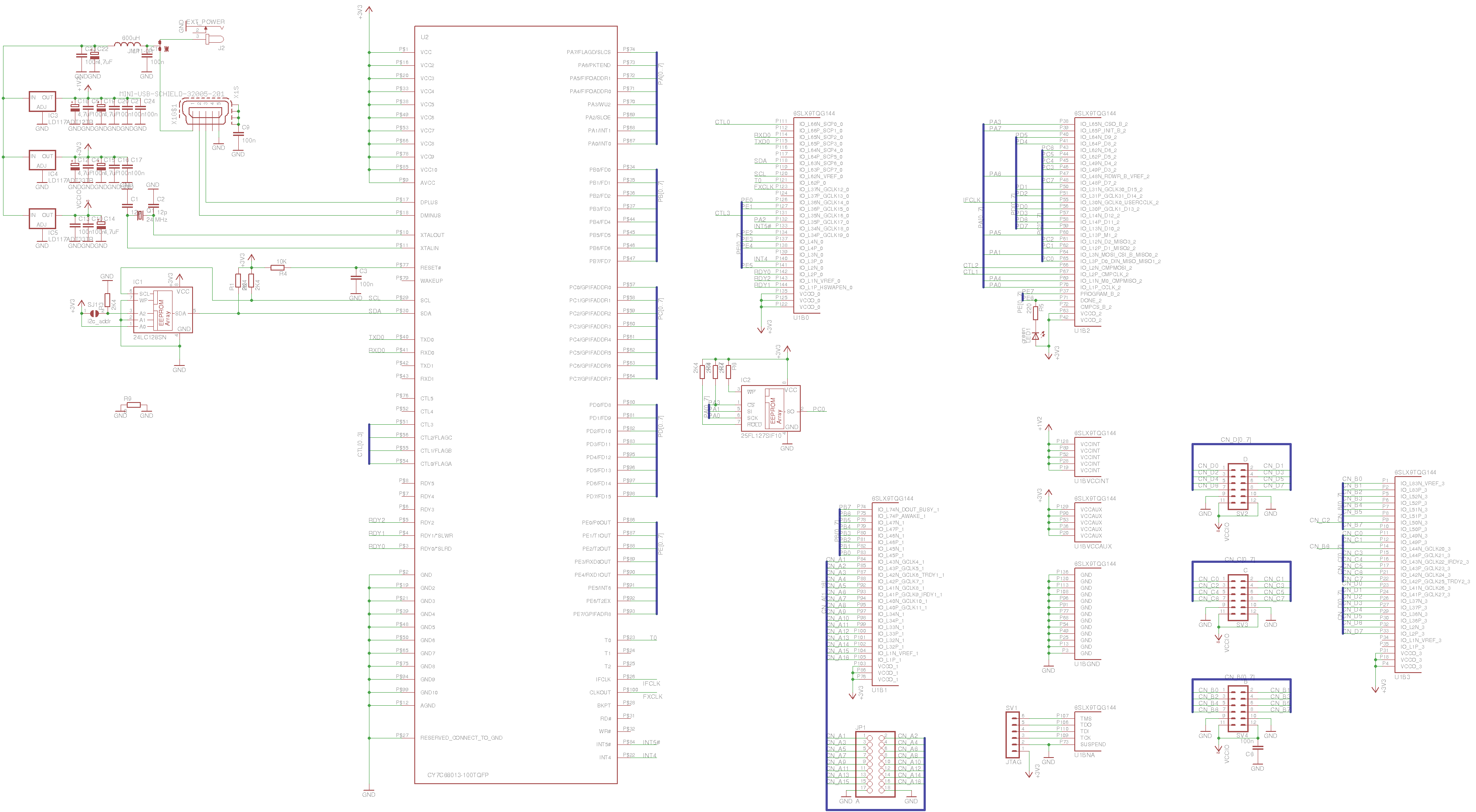
Schematic and PCB
The demo design consists of 2 boards:
- Logic board: Cypress FX2 + Xilinx Spartan6 (XC6SLX9). Eagle files: FX2_LX9.tar.gz This logic board can be used independently for FPGA learning/experimentation, since it's having 3 Digilent-PMOD connectors and very similar to ZTEX USB-FPGA Module 2.01. The difference - is using lower-end FPGA with soldering-friendly LQFP 144 box. You don't need to install neither EEPROM nor FLASH due both firmwares are uploaded during initialization procedure by the software.
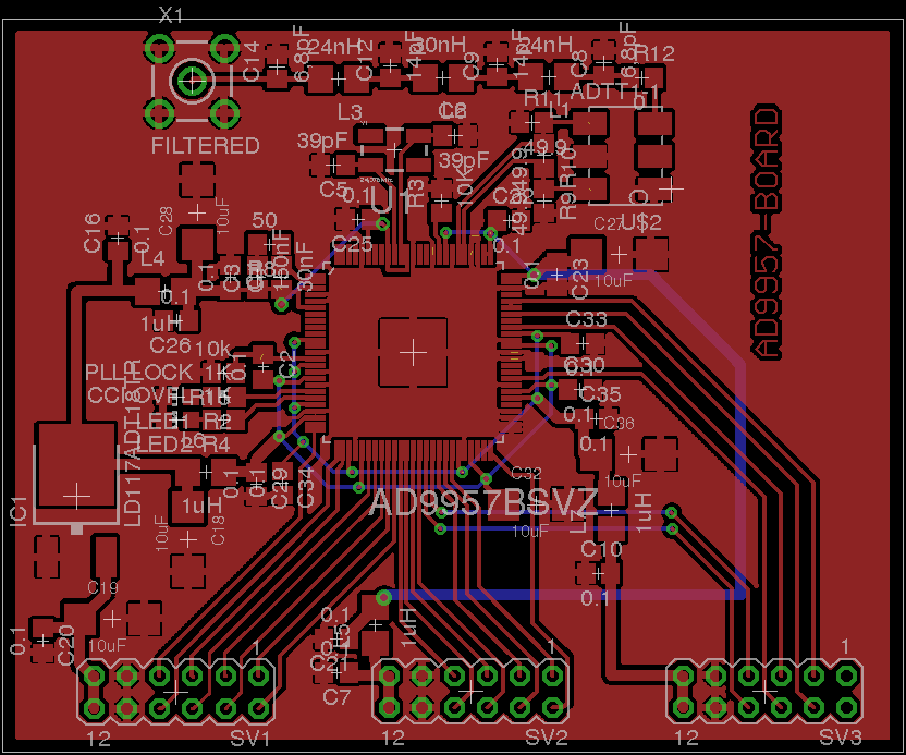
- Radio Board: AD9957 quadrature upconverter and RF-filter. Eagle files: ad9957board.tar.gz
Logic Board:
Radio Board:

Software and other tools:
PC-Software sources with pre-compiled firmwares included: dab_blockpart.tar.gz
To compile this project You need libusb-dev library installed. Just run "make" to create binary. Only linux is supported as base system for this software rightnow.
FX2-Firmware sources: passthru_sch.tar.gz
To generate FX2 firmware hex-file, you need ZTEX SDK, so do the following:
$ wget http://www.ztex.de/downloads/ztex-140813.tar.bz2
$ tar -xvf ztex-140813.tar.bz2
$ cd ztex/examples/usb-fpga-2.01/2.01b/
$ wget http://tipok.org.ua/sites/default/files/EasyDAB/passthru_sch.tar.gz
$ tar -xvzf passthru_sch.tar.gz
$ cd passthru_sch
$ make
FPGA Bitstream sources (ISE project): passthru_sch_iseproj.zip. To generate bitstream, open this ISE project and run "Generate Programming File" task. After it successfully completed, you will find "passthru_sch.bit" file, which you can use as bitstream for feeding FPGA. Optional sources of high-level synthesised blocks (if u want to modify c-sources instead of verilog's), that is used in this project avaliable here.
To manipulate ETI-streams, you can use eti-tools and dabtool. If any manipulation is not needed, then just use ODR-DabMux to create your own multiplex.
Usage examples (run pc-application with sudo of needed):
# dab_blockpart eti_stream.eti -l -A 1.0 -F 194.064 -B "passthru_sch.bit.mod" -H "passthru_sch.ihx"
Where:
"eti_stream.eti" - is pre-created eti file with few stations, which will play in-loop.
passthru_sch.bit.mod - is bitstream file for FPGA, which must be inside of the directory, from which application is started.
passthru_sch.ihx - is hex file, which will be uploaded to the FX2 processor.
The output signal will be avaliable on 7D DAB channel (194.064 MHz).
Additionally, there is firmwares that don't do any modulation and just passing the input data to the DAC, this has been made just for testing boards and not needed anymore.
All sources will be uploaded into GitHub soon.
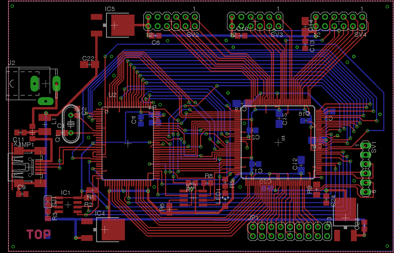
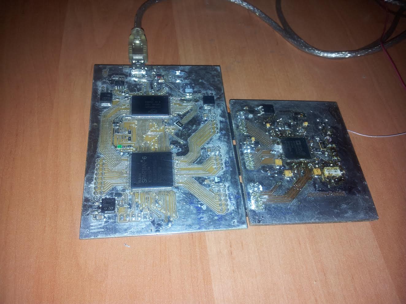
Resulted photo of demo PCB:
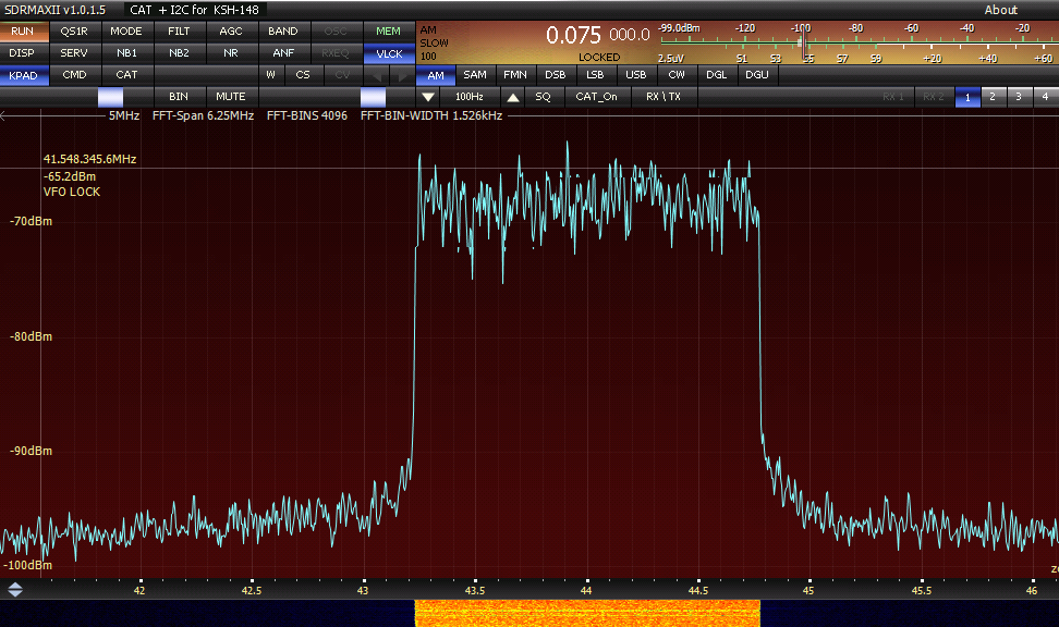
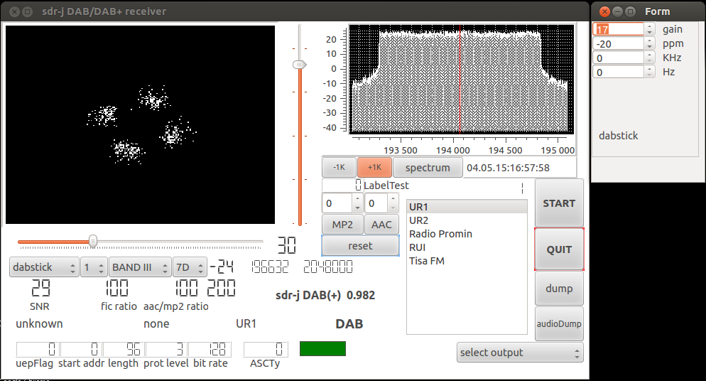
Created signal results:
Signal on QS1R SDR receiver (used as spectrum analyzer) and SDR-J application, used with RTL-SDR USB stick:
TODO and Known Issues:
- The current DAC samplerate of AD9957 is 516.096 MHz. It is possible to add FIR filter into the block design, so we can bring up DAC samplerate up to 1Ghz.
- Only DAB Mode I is implemented. There is no nearest plans to enable other modes.
- It is possible to decrease FPGA resources by disabling gain normalizer and use full precision output after iFFT.
- It is possible to move all parts of modulator into FPGA, so there is no need for software at all.
- Add u-blox LEA-M8F GPSDO and try to make SFN network transmission.