- Log in to post comments
 Introduction
This is a list of ideas for creation of DRM+ receiver on low-cost component base that will utilize minimal power to be ready for making pocket receiver.
[PRELIMINARY TOPIC]
Here is requirements to future receiver:
- Work in FM OIRT band: 65.8...74 MHz, due this band have free RF space for test transmitter that will emit DRM+ signal here.
- Consume low-power to be battery powered and work at least 8 hours from it.
- Sensitive enought to receive signal and reject unneedded regular FM-stations that work in this band.
Receiver block design:
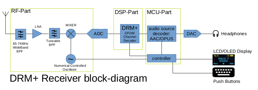
The whole receiver can be splitted into 4 parts:
- RF signal downconverter.
- DAC with 12...24 bits resolution for I/Q channels.
- DRM+ DSP demodulator, that converts digitized I/Q flow to bitstream that contains FAC/SDC/MSC data or does this job partially, like synchronization + FFT.
- Microcontroller with additional DSP instructions that will be able to post-process bitstream from (2) or (3) and decode audio stream.

Implementation ideas:
1+2 a). RF-frontend with ADC, Variant 1:
So idea 1, and most realistic:
To use Silabs SI4777 or NXP TEF6659/TEF6688 as reception front-end. This frontends - are very easy to make for DRM+ solution, because it doen't require lot of additional components, and work as-is. But from datasheet info, it consumes ~1W of power, so battery leakage will be huge. Since SI4777 is most documentation-open, it's better to use it.
1+2 b). RF-frontend with ADC, Variant 2:
To use AD9876 as RF-downconverter and DAC. This variant taking very low power, but needs additional components, like:
Input RF preamplifier and band-pass filter to reject image frequency at 6.5MHz offset. So band-pass filter must be tuneable (with varactors) which tune frequency will be changed in-parallel with VCO's frequency. Such design promises to be most intermodulation - strong, because unneeded frequencies will be rejected by classical analog-way.
1+2 c). RF-frontend with external ADC, Variant 3:
To use LTC5506 or other quadrature demod with SI514 i2c controlled oscillator. This variant is like UHFSDR, with classic way of SDR receiver, where ADC can be inside processor (in most cases they have 12bit), or external one, like TLV320AIC3254 or TLV320AIC3204 or even USB sound card. The most important thing - is to allow to convert on frequencies at least 128 KHz, so whole DRM+ signal will be visible on software side.
3 a). DSP algorithms in Xilinx Spartan 6:
By using Xilinx Spartan6 as base development platform for initial tests. My hand-made board with Cypress USB-controller and XC6SLX9 will be used.
3 b). DSP algorithms in Latticce ICE40 UltraPlus:
Main difference with Xilinx Spartan6 - is chip size (ICE40UP5K-SG48ITR is QFN48! comparing to LQFP144 of Spartan6), and power consumption is lower on this chips. Also it gives less space: 5K logic elements and 8 DSP elements with 256kB of block-ram, but it mist be enought for FFT and sync. Can be tried on breakout board.
3+4 c). Use DSP algorithms in ESP32:
This CPU is actually better for using in (4) but if dual-core power would be enought, it's pretty fine to use it as part of DSP. It have integer-based math and hardware multiplier as well as 512kB of RAM.
3+4 c). Use Allwinner V3S as main processor and DSP:
This Cortex-A7 with 64MB embedded on-chip RAM - is very powerful for doing all-in-one. And I'm pretty sure that it's not getting lot of power during operationing. But hard to get documentation.
3+4 d). Use PIC32MZ2048 as DSP and main processor:
This MCU is MIPS-based with additional DSP instructions and have 512KB of RAM, great for developing of such design. Can be tried on Olimex PIC32-EMZ64 low-cost board.
3+4 e). Use STM32F7 or STM32H7 as DSP and main processor:
This MCU's are well-known and have big community, also have enought I2S interfaces and DSP instructions, but they are not so great in price point of view as other competitors in this list.
To be continued...
