Introduciton
This page describes hardware and software design for digital USB FM transmitter, called FmStick. This hardware does not contain analogue parts (except RF part). The main idea - is to create transmitter, that looks like usb flash stick. This idea is not new, You can see some of this designs in market, like Griffi RocketFM or Keene USB FM Transmitter, both avaliable on Amazon. But device, described below - is different. It does not have analogue sound parts at all, and it supports RDS, and it is powerful. The main features of this device are:
- Transmit Frequency: 76 ... 108 Mhz.
- Transmit Power: -60 ... 20 dBm[1].
- Audio Compression: Yes
- Audio Limitation: Yes
- Audio Signal Measurements: Yes
- Pre-Emphasis: 0/50/75 uS.
- RDS: Yes
- RDS RadioText: Yes
- RDS Time: Yes
- Drivers Installation Needed: No[2]
- Software Needed: No[3]
- LEDs That shows state: Yes
- External power needed: No
[1] Maximum ERP allowed by E.T.S.I. In Europe
[2] If You don't have pre-programmed EEPROM chip, then You need to use DFU-Util to load firmware into EEPROM. This operation have to be done only once and only on case when You have clear EEPROM.
[3] You may save transmitter configuration parameters (such as frequency, power, RDS info and audio compressor/limiter values) into EEPROM. If You do this, You dont need FmStick software to run Your transmitter. It will auto-load this configuration when FmStick hardware connected to computer.
NOTE: Right now i'm developing new FM-transceiver project, based on SI4721 and STM32 chips. Be on line!
Hardware Description
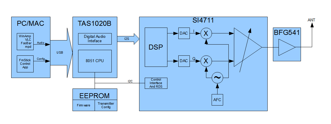
This is the block diagram, that illustrates transmitter design.
As You can see, that device consists of 2 main chips: TAS1020B and SI4711 (frontend). There is also 24LC64 memory chip, where firmware and transmitter configuration saved. The sound, generated by PC or MAC goes through USB into TAS1020B chip, where it's converted into I2S digital interface, then it goes into SI4711 FM transmitter chip, where it's prepared for tramsmission (it's compressing, limiting, and pre-emphasing). Then FM carrier modulates by this digital sound.
The SI4711 dies not contain classical FM-modulation schematic (that contain variable-capacitance diode), instead of it, there is modern I/Q-modulation scheme, where DSP controls amplitude and phase of the FM carrier. Also after RF created, it goes into BFG541 where it's amplified to ~20dBm (100mW). This scheme (that use I/Q-modulator) gives dramatically improvements of transmission quality, somtimes even better that commercial FM-broadcasts.
Device using USB-Bus as power source, and maximum current is 200mA (in maximal transmitting power). It has 5 leds that indicates:
- Yellow: Frontend chip powered up (blinking).
- Blue: Transmitting.
- Yellow: Silence detected.
- Green: Sound is presented.
- Red: Overmodulation occurs.
Schematic and PCB
The full schematic of device:
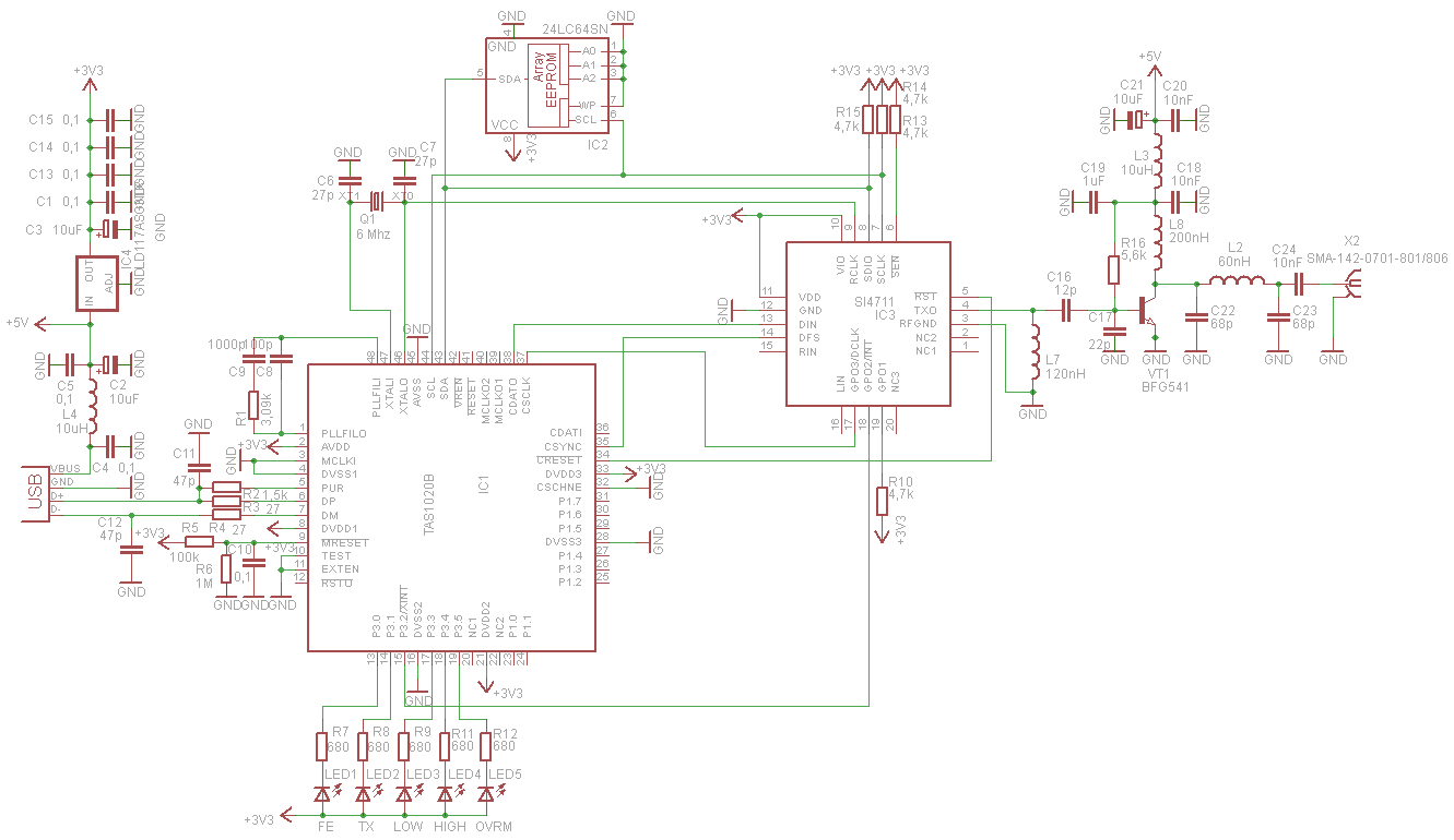
Take care about IC's names, that you may buy:
- Processor: must be TAS1020A or TAS1020B. Just TAS1020 (without last leter) - will not works!
- Transmitter: The tested samples - are: SI4711-A20-GM/SI4711-A20-GMR. Also (maybe) will works this chips: SI4711-B30-GM/SI4711-B30-GMR and SI4713-A20-GM/SI4713-A20-GMR or SI4713-B30-GM/SI4713-B30-GMR. Other chips (SI4711-A-GM/SI4711-A-GMR and all versions of SI4710/SI4712) - does not support digital sound, that's why we can't use them (but we able to add some DAC's but it would be workaround, not a solution).
- EEPROM: Simple 8KBytes i2c-memory chip: 24LC64.
The PCB is created as sigle-sided board with few bridges at the bottom side. It must be created by "photoresist" method because there is very thin conductors:
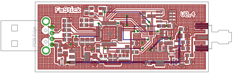
The ready-to-print pdf: FmStick-normal.pdf same, but mirrored: FmStick-mirrored.pdf
Full Eagle project: FmStick-22.11.2011-pcb.tar.gz
Firmware
The latest firmware is: FmStick-r1.343-firmware.zip (don't forget to extract it).
FmStick firmware 1.343 changes (20.06.2013):
- Swapped L/R channels.
- Enabled AUX-in feature (stand-alone mode).
Installing firmware
If You have already pre-programmed EEPROM, or if you program it with You I2C-programmer, like IC-Prog or PonyProg, you don't need to install anything.
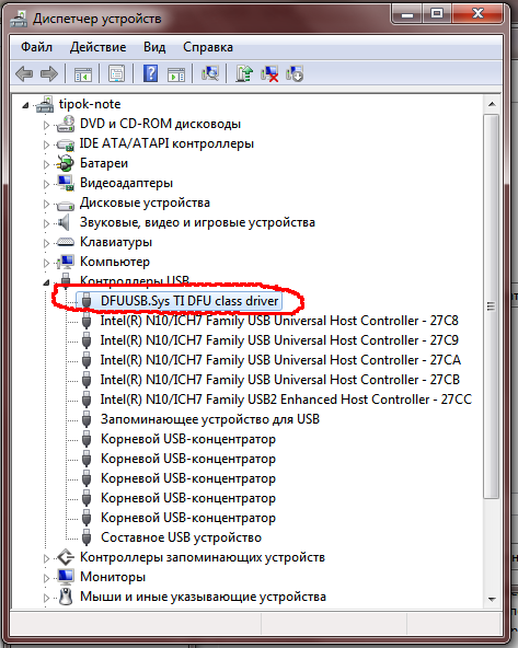
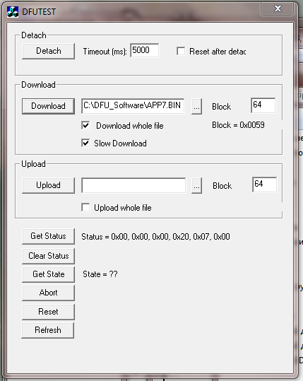
If You have clean device (not programmed yet), and You are too lazy to solder I2C-Programmer, then You must install firmware into device using DFU-Software provided by TI, and install DFU driver (If You have Windows 7, this driver installed automatically from windows software-center). After driver installed, run DFUTEST.EXE, You will see application UI. The next pictures shows device firmware installation steps:
 |
 |
 |
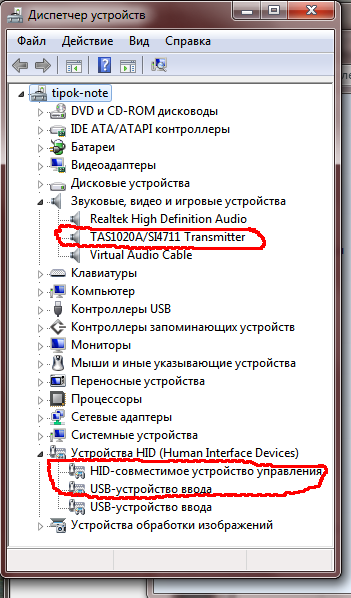 |
| Device dispatcher showing FmStick without firmware. DFU-driver used. | DFU-Application with various flags. Here You must select file in "Download" area, to load firmware into device. | DFU-Application, completes loading firmware into device. | Device dispatcher after updated firmware (You must un-plug and plug FmStick into USB!). |
After installing the firmware, the device drivers are no longer need. So You can connect FmStick ( for example to another computer), on which nothing is installed (well, except for programs for controllong it).
The firmware - is open-source, but due using proprietary code from TI, I can't publish sources. If You need source code, You must be registered TI member. If You are already member, contact me, and give You profile page from e2e.ti.com, after that, i'll send firmware sources to this profile.
Software
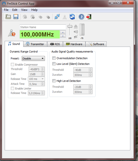
The software written in Qt4 and works on Windows/Linux/MacOS. Also it's GPL V2 Licensed and open-source. It has 3 UI-modes:
 |
.png) |
 |
| 1). The normal window of the FmStick application (device is not connected) | 2). The minimal UI-window of the FmStick application (device is connecter, transmitting, and audio is presented) |
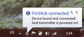
3). FmStick is hidden to System Tray, and it sending signal, that device is founded and transmission is enabled. |
Supported languages are: English, Russian, Ukrainian.
Pre-Compiled versions of FmStick control application:
Windows:
- Installer Package: FmStick-1.0-setup.exe
- Archive with files: FmStick-1.0.zip
Linux:
- Download deb-files from: fmstick_1.0-1_amd64.deb
- You also may compile application from sources below.
FmStick control application source code:
You may download Qt4-project with source code from this link:fmstick-1.0-src.tar.gz
So do not forget to satisfy dependencies of the application: libqt4-dev, qt4-dev-tools, qt4-qmake, cmake, libusb-1.0-0-dev
Development tools available on the website: qt.nokia.com
Source code repository:
Project on Github: https://github.com/piratfm/fmstick
Limitations/Problems
Device:
- The internal I/Q DAC's are not clear-filtered, this makes output spectrum a little dirty with parasitic harmonics and digital noise, look at spectrum diagram below.
- If You transmitting audio from a laptop with maximal power, Your WiFi-connection may not works due interference.
- The temperature of device sometimes rises 35°C, this due small size of device and lack of cooling system (radiator).
Software:
- When PC goes to sleep-mode, the application hangs. This problem occurs because we using so-called "blocking communications" with USB-device.
- When "live editing" selected, the interface is a little slower, because each change of parameters - is sent to device. This is most noticeable when we change RadioText or station name (PS).
Spectrum Diagrams
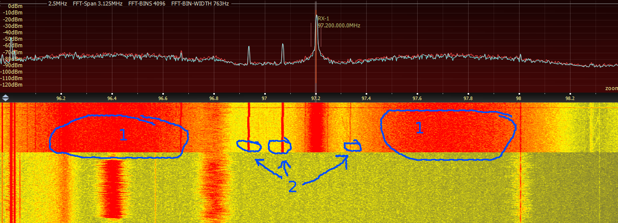
2,5 MHz Spectrum, 97,2 MHz Carrier only. Transmitter switched on:
1 - digital noise, 2 - parasitic carrier frequencies
2,5 MHz Spectrum, 97,2 MHz Carrier + pilot-tone + L-R + RDS:

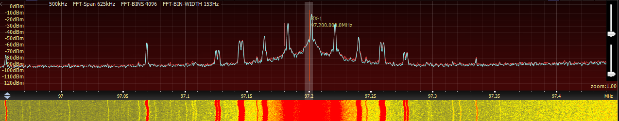
0,5 MHz Spectrum, 97,2 MHz Carrier + pilot-tone + L-R + RDS:
FmStick hardware in market
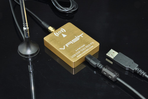
If you wish to buy ready-made device, called HiFi-FMT V-FMT212R RDS HiFi FM Transmitter(HiFi-FMT) that have 1:1 hardware and software design, You can follow VAST internet-shop:
- Direct site location: http://www.vastint.com/product/V-FMT212R_HiFi_FM_Transmitter_RDS_HiFi-FMT-RDS.html
- Ebay Store: http://stores.ebay.com/VASTELEC
- Aliexpress: http://www.aliexpress.com/store/515229
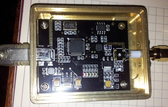
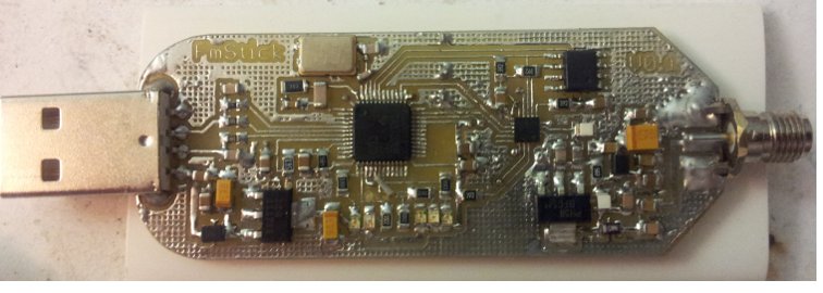
Prototype Board Images
The Real-Life photos of prototype (TOP-view):
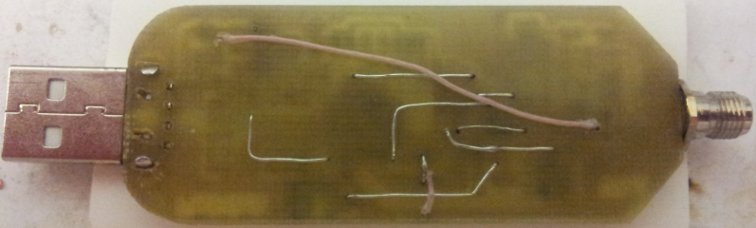
The Real-Life photos of prototype (BOTTOM-view) nothing interesting here:
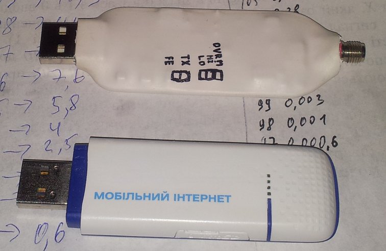
The prototype inside thermo-shrink near 3G modem: